Simplified Bolts
Table of contents
About
The Simplified Bolts is a load feature where so-called “Simplified bolts” are created and placed in a group folder in the current structural (or thermal) analysis. The Simplified Bolt is constructed of BEAM188 solid circular for the bolt shaft and a CERIG or RBE3 remote points for the head and nut/thread. New in 2025 R1 is that any matching “Remote Point” will be used. This will allow for more advanced usage combining connections and bolts as well as Condensed parts.
In thermal analysis LINK33 is used. This is similar as the standard Beam connections in Mechanical.
The additional features with the Simplified Bolts compared to “Beam connection” are that:
- All Simplified bolts are saved in one place, the “Simplified Bolts Group” folder.
- Multiple bolts can be defined in one load object, i.e. all M12 bolts of the model.
- A point mass (MASS21 element) can be added to the bolt head to account for missing mass.
- Pretension can be automatically calculated based on selected bolt code, material and shaft diameter.
- Thermal loads on the bodies will be mapped to the bolts to account for correct thermal elongation.
- Post processing of the Simplified bolts is done using the Bolts Strength or Bolts Fatigue object.
Usage
Click on “Simplified Bolts” in the toolbar to insert the Simplified Bolts Group folder in the current static analysis as well as creating the first Simplified Bolts load object.
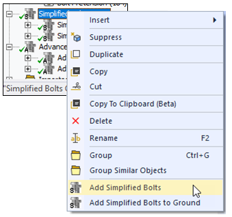
To add additional bolts, right click on the Simplified Bolts Group folder and select “Add Simplified Bolts” or click on “Simplified Bolts” in the toolbar again. You can also use “Duplicate” on an existing Simplified Bolts and modify the properties.
There is also an option Simplified Bolts to Ground used to connect a body to ground, e.g. when using compression only support.
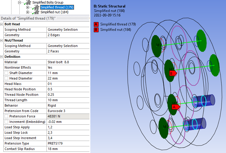
Inputs to define the Simplified Bolts and Simplified Bolt to Ground are:
| Bolt Head | |
|---|---|
| Scoping Method | Geometry Selection/Named Selection (i) |
| Geometry | Planar or conical faces OR edges connected to non-cylindrical faces OR nodes. (ii) |
| Nut/Thread | |
| Scoping Method | Geometry Selection/Named Selection |
| Geometry | Planar or conical faces OR edges connected to non-cylindrical faces (Nut) OR cylindrical faces (Thread) OR nodes. (ii) |
| Bolt Geometry | |
| Shaft Diameter, ds | Bolt shaft diameter that defines the circular solid section for the beam element. |
| Hole Diameter, d0 | Sets the hole search diameter if using “face selection” and is also used as the hole diameter in Bolt Strength results. |
| Head Diameter, dm | Sets the maximum size of the bolt head and nut. |
| Head Node Position | Head node offset factor relative to hole plane. Offset = Factor*Shaft Diameter |
| Thread Node Position | Thread node relative position 0: Beginning, 0.5: Middle (default) 1: End |
| Thread Length | Thread engaging length symmetric around the thread node. (If 0 use full thread) |
| Bolt Length | Length of bolt shaft. Only visible for Bolts to Ground. |
| Bolt Properties | |
| Material | Select material from “Engineering Data” or app default materials. |
| Nonlinear Effects | No (Default)/Yes. Use plasticity models defined in the selected material (iii) |
| Head Mass | Add the missing mass (optional). |
| Behavior | Rigid/Deformable/Beam/Custom. |
| Symmetry BC | No (Default)/Auto/Yes. Identify symmetry plane bolts. |
| Bolt Pretension | |
| Pretension from Code | Select a code to get the recommended pretension force based on Shaft Diameter and Material. Default “None”. |
| Pretension Force | Initial bolt force. If zero, the pretension section is locked. |
| Increment (Embedding) | Pretension adjustment increment. If Increment > 0 force increase. (iv) |
| Load Step Apply | Load step to apply the pretension force. Used only if Pretension Force > 0. (v) |
| Load Step Lock | Load step to lock the bolt adjustment. (vi) |
| Load Step Increment | Load step to add the Increment (Embedding). Used only if Increment ≠ 0. (vi) |
| Pretension Type | Program Controlled (Default)/Pretension (PRETS179)/Joint (MPC184). Use MPC184 if there is large deformations or rotations. |
| Definition | |
| Contact Slip Radius | Radius used for normal and slip contact force summation. (vii) |
| Bolt Count | Number of bolts created. (Read only) |
(i) Scoping Method
The manual “Geometry Selection” can be converted to a “Named Selection” using the context action “Promote to Named Selection”.
(ii) Geometry
Both shell and solid bodies are supported. If selecting faces the “Shaft Diameter” and “Hole Diameter” defines the range for automatic hole edge search.
The bolts can have different orientation and the pretension normal will be set for each individual bolt.
The global Bolt face angle tolerance for the head/nut can be modified in Bolt Settings.
The head and nut/thread must only have one unique match between head and nut.
Half circles and cylinders at symmetry planes can be selected.
Virtual Topology or External Models (faceted geometry) is not supported.
Nodes from a Condensed Part can be selected.
(iii) Material
The following material properties (and corresponding MAPDL MP Lab) are supported: Young’s Modulus (EX), Poisson’s Ratio (NUXY), Density (DENS), Coefficient of Thermal Expansion (ALPX), Thermal Conductivity, (KXX), Specific Heat (C), Isotropic Hardening (BISO & MISO), Kinematic Hardening (BKIN, KINH). If orthotropic properties are defined the X component is automatically used (EX, NUXY, ALPX & KXX). The Bolts Pretension can be used in a thermal analysis to apply the bolt material. The pretension settings are ignored in this case.
(iv) Increment (Embedding)
You may use Increment (Embedding) as “Preadjustment” if Pretension Force = 0 and Load Step Increment = 1.
(v) Load Step Apply
The Load Steps may be defined as a “series” to define a sequential bolt pretension.
(vi) Load Step Lock The analysis must have at least two load steps to use the Pretension Force and Lock and two or three load steps if also using the Increment.
You can use the Pretension Force and only one load step if you set Load Step Apply = 1 and Load Step Lock = 2.
(vii) Contact Slip Radius
The Head Diameter is used as default radius. The solution is not invalidated if changed but a solved bolt result object must be cleared and re-evaluated to see the changes in contact normal and slip force.
A property file is also written to the solver files directory that is used by the Bolt Report feature.
Graphics
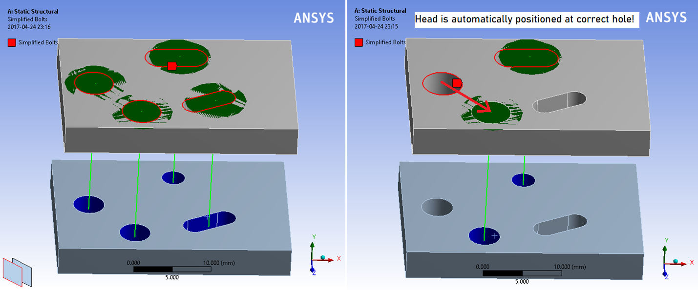
A graphic representation is created once valid inputs are given. The Simplified Bolts load object searches to connect the head and nut with the minimum distance and matching hole axis. The head geometry is plotted in red and the nut/thread in blue. The head and nut diameter are plotted as a disc (normal to the bolt shaft) and the bolt shaft as a green cylinder. If the Thread Length is given turquoise circles are plotted to indicate the thread engagement. The Contact Slip Radius is plotted as a purple circle at the plane for the pretension section.
The bolt Id number is printed at the center of each bolt head. This number is used in the result tables. The colour, translucency and printing of “Id” number is defined in the Bolt Group object. The display of all bolts in the Bolts Group can be disabled by setting “Show Graphics = No”. The default values for the group can be defined in the Bolt Settings.
The head centroid (and disc) is adjusted to be on the axis from the corresponding thread/nut. If selecting non-matching head and thread geometry the app may still create valid bolts if the bolt head plane is the same.
Simplified Bolts with Nut
The Simplified Bolts with Nut works in the same way as the Simplified Bolts except that is only uses one scoping Bolt Head and Nut that can use Nodes, Edges and Faces to identify the bolt holes.
It uses the Max Bolt Length as a limit when matching bolt holes and will use the smaller hole as reference for the bolt axis.
This feature is useful when wanting to connect a large number of (shell) parts without having to separate the scoping for head and nut.
Simplified Bolts to Ground
The Simplified Bolts to Ground works in the same way as the “Beam Body-Ground”. Based on the Bolt Head scoping and Bolt Length bolts are created and pretension force can be applied just as for the standard Simplified Bolts. In a structural analysis the end of the bolt is locked in all degrees of freedom.

In both structural and thermal analyses, the environment (or initial) temperature is applied to the fixed end of the bolt and the temperature will be interpolated along the bolt shaft.
Create Washer Mesh
A “Washer” (or “Quad Layer”) mesh imprint around the bolt holes can be added using the context action “Create Washer Mesh” for an individual bolt object or on the Simplified Bolts Group.
If updating the scoping for the bolt you may use “Create Washer Mesh” again to apply the changes.
The created mesh object may be edited if needed, e.g. to change the “Number of Divisions” or “Number of Washer Layers”. For shell parts a “Quad Layer” is used and for solid parts “Sizing”, “Face Meshing” and “Inflation” objects are used.
To delete the mesh object use the context action “Delete Washer Mesh” (or delete individual objects in the model tree).
Set the Mesh>Automatic Method “Sheet Body Method = PrimeMesh” or assign the mesh “Method = Automatic (PrimeMesh)” to the shell parts.
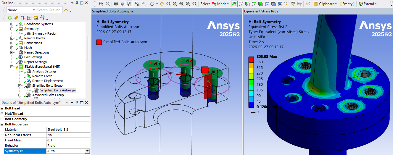
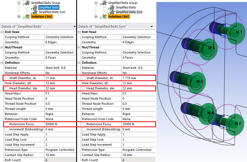
Simplified Bolts and Symmetry
Using “Symmetry BC = Auto” will identify all bolts with a single half circle edge at the bolt head as symmetry bolts. Using “Symmetry BC = Yes” will identify all bolts in the group that has a half circle or slotted hole as symmetry bolts. The graphics will mark symmetry bolts with a red plane along the bolt shaft. A symmetry bolt is meshed with beam elements with half the stress area the cut plane nodes are constrained in the normal direction as well as for out-of-plane rotations. The pretension force is automatically reduced to 50% for the symmetry bolts.
Legacy workaround method for symmetry
Simplified Bolts (and Rivets) can be defined on the symmetry plane in a model by following these steps.
-
Define the symmetry plane using a selected coordinate system.
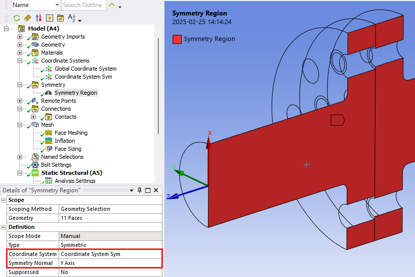
-
Define one group of bolts using the half circles and cylinders at the symmetry plane.
Define the “Shaft Stress Diameter” so that the area is half of the nominal area, ds_sym = ds/sqrt(2)
Define the “Pretension Force” to be half of the nominal pretension force.
Bolts outside of the symmetry plane is modelled as normal.
-
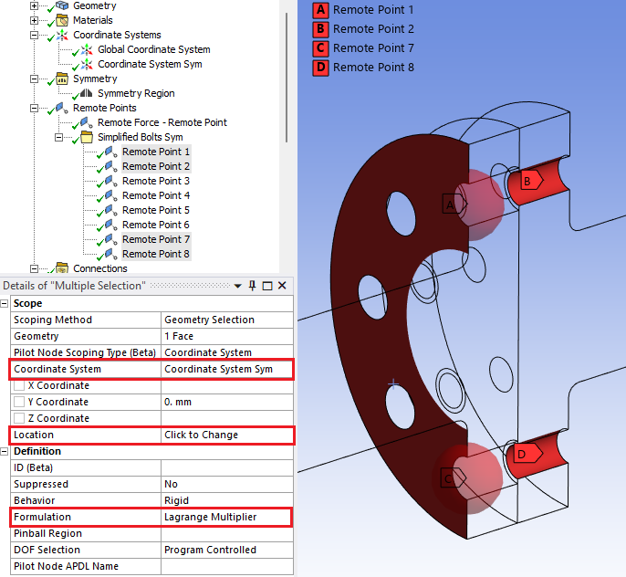
Create Remote Points at the head and thread for each bolt at the symmetry plane. Bolts (and Rivets) will use existing Remote Points instead of creating new ones.
Tip: Use the context action “Promote to Beam Connections” on the “Simplified Bolts Sym” to create the Remote Points and Beam Connections. Then unsuppress the “Simplified Bolts Sym” to keep the Remote Points. -
Edit the Remote Points so that they use the same Coordinate System as the Symmetry Region and re-align the position using “Click to Change”.
Also change Formulation to “Lagrange Multiplier” to avoid over constraints at the symmetry plane.
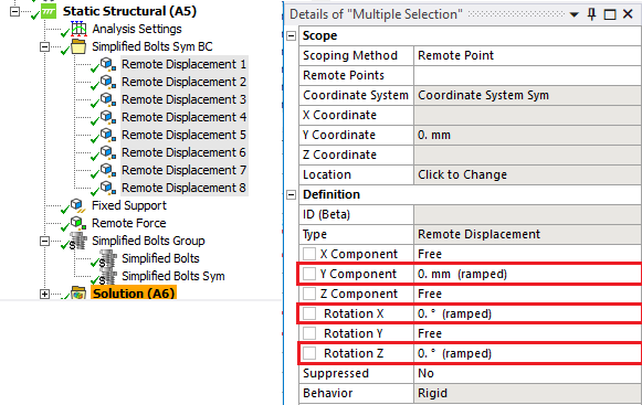
-
Create a Remote Displacement for each Remote Point and apply the corresponding symmetry constraints.
-
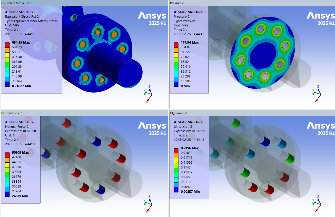
Solve the model and post process as normal.
Force and moment values will be listed/plotted as half of the nominal value.
Stress and utilization factors will be listed/plotted as normal.
Tip: Use the Grouped Result to display the selected results for all bolts at once.
 Resolve Solution Convergence problems
Using Rivets or Simplified bolts will add beam elements to the FE-model. This will influence the moment convergence. Using the default setting “Program Controlled” for Moment Convergence in Analysis Settings/Nonlinear Controls may result in long solution time or un-converged solutions for certain types of models and loads.
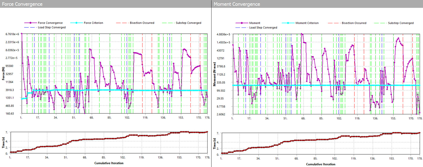
Review the Solution Output: “Force Convergence” and “Moment Convergence” for the first pretension step to find the convergence criteria value “Force Criteria” and “Moment Criteria”.
If the “Moment Criteria” drops to a very low value for load step two and up and the solution struggle to converge you may assign a manual value. See the red ring in the plot!
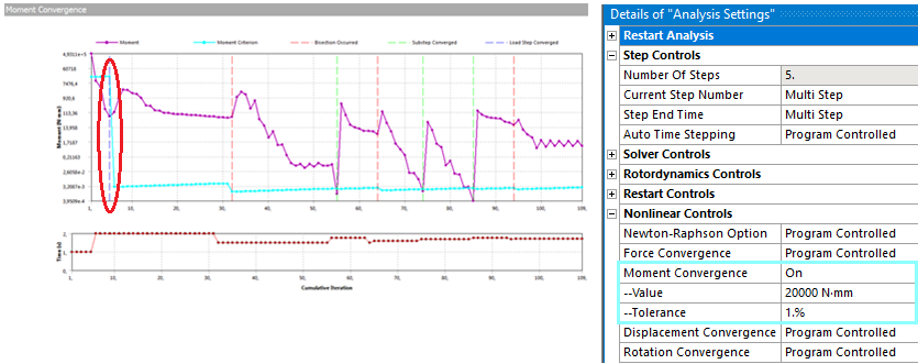
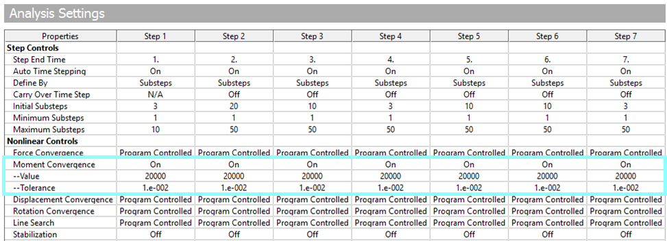
Assign Moment Convergence “On” and set the “Value” and “Tolerance” for all load steps to have manual criteria. The “criteria” is defined from “Value*Tolerance”. In this case Value = 20000 and Tolerance = 1% gave a similar convergence behavior for both Force and Moment.
Tip: Click on “Analysis Settings” and then “Worksheet” button to review settings for all load steps.
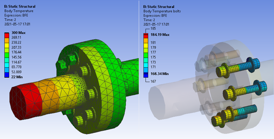
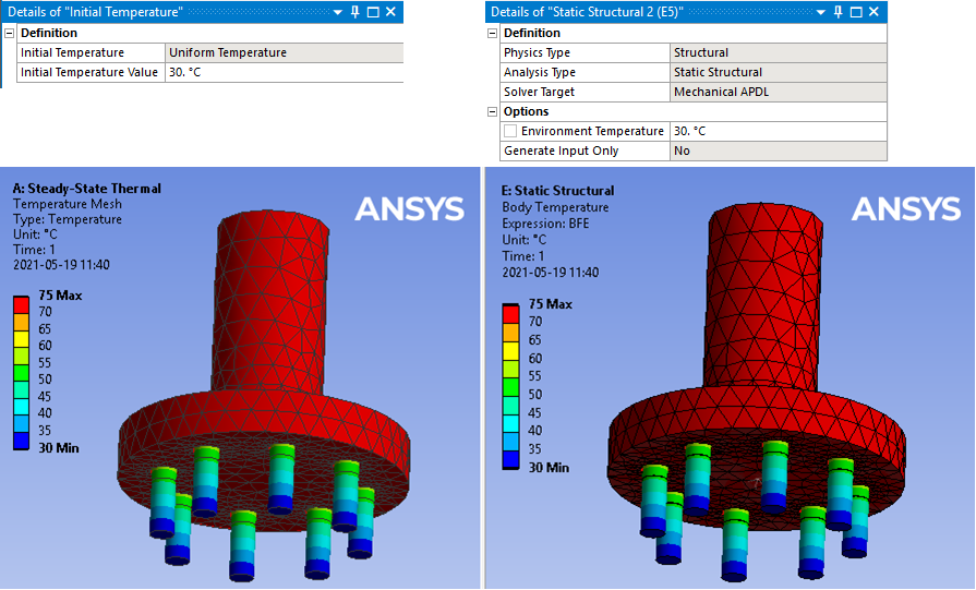
 Mapping of thermal loads
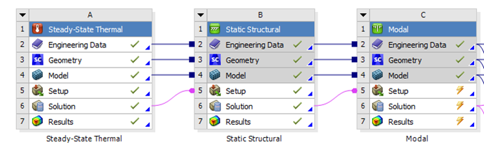
If using an upstream thermal analysis linked to the structural analysis with “Imported Body Temperatures” and/or “Thermal Condition” the temperatures will be automatically mapped to the rivet and bolts. Temperatures will be interpolated over the bolt using the head and thread/nut temperatures.
It is recommended to use “Behavior = Beam” to avoid thermal constraint loads from “Rigid” or convergence issues from “Deformable” behavior.
Deactivating the thermal load from a load step is not supported for rivets/bolts and the existing temperature from last load step will remain active. Instead set the temperature back to e.g “room temperature”.
If using a mix of imported and thermal conditions, like in the figure below, each part of the bolt/rivet will have constant temperature based on its connected part. For a solid bolt the entire bolt will have constant temperature up to the pretension split based on the connected parts thermal condition at the bolt head and thread respectively.
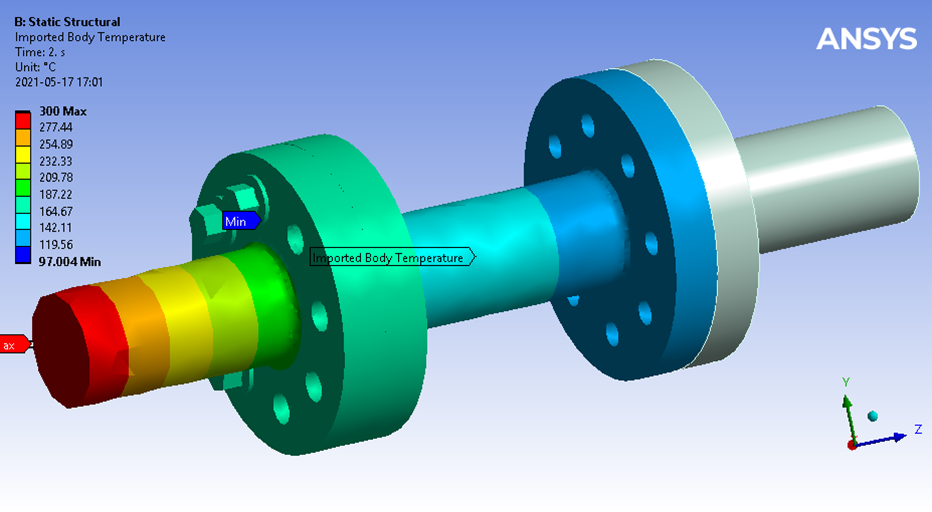
Detail of mapped temperatures with interpolated temperatures on the advanced bolts.