Bolts Fatigue
Table of contents
About
The “Bolts Fatigue” object adds the fatigue post processing features to the Bolts Pretension, Simplified Bolts and Advanced Bolts load objects.
This result object will extract all relevant information from the selected bolt joint group and create a results summary listing. It also includes the Eurocode 3 S-N curves for fatigue life evaluation of the bolt stress range.
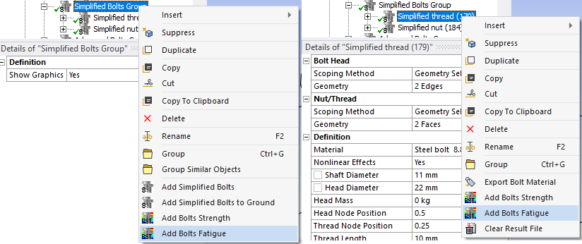
Usage
Bolt result objects for all bolts in the Child Setup, Bolts Group or a selected Bolt object can be added using the context action “Add Bolts Fatigue”.
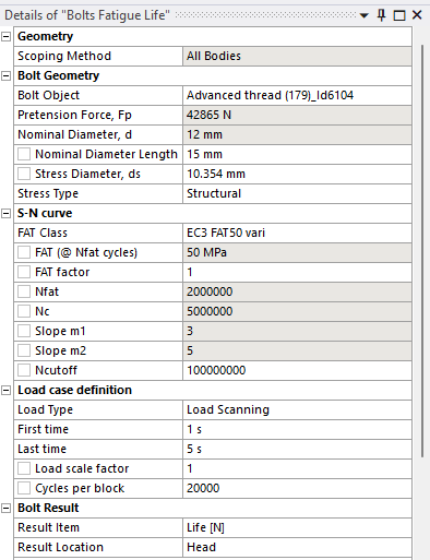
Inputs to define the Bolts Fatigue are defined in the table below.
| Geometry | |
|---|---|
| Scoping Method | All Bodies (Default)/Geometry Selection/Named Selection |
| Geometry | Faces/Bodies to display results on (i). |
| Bolt Geometry | |
| Bolt Object | Select a Bolt object from the list (ii). |
| Pretension Force, Fp | Nominal applied pretension force (read only). |
| Nominal Diameter, d | Shaft nominal diameter used in evaluation (read only). |
| Nominal Diameter Length | Length of unthreaded bolt shaft with nominal diameter (can be changed). |
| Stress Diameter, ds | Shaft stress diameter used in evaluation (can be changed). (iii) |
| Stress Type | Normal/Structural (Default)/Shear |
| S-N curve | |
| FAT Class | Select a FAT class (Default EC3 FAT50) (iv) |
| FAT factor | Scale factor for FAT value (1.0). E.g. to apply a thickness or temperature modification factor (iii). |
| FAT (@ Nfat cycles) (*) | Stress range at Nfat cycles (50 MPa). |
| Nfat (*) | Number of cycles for defining FAT (2E6) |
| Nc (*) | Break point between slope m1 and m2 (5E6). |
| Slope m1 (*) | S-N curve slope for N < Nc (3). |
| Slope m2 (*) | S-N curve slope for N > Nc (1e6). |
| Ncutoff | Maximum calculated life (1E8). |
| Load case definition | |
| Load Type | Select a Load Type (Default “Load Scanning”) |
| Loading Ratio | Factor to define custom range. Visible for Load Type “Ratio”. (Default = -1 Fully Reversed) |
| First Time | Visible for all Load Type but “Solution Combination” or “Solution Scanning”. (Default = time of Load Step Apply. (v) |
| Last Time | Visible for Load Type “Fatigue Combination” and “Fatigue Scanning”. (Default = Analysis end time). (v) |
| Solution Editor | Table editor. Visible for Load Type “Solution Combination” and “Solution Scanning”. |
| Load scale factor | Fatigue stress scale factor. (Default = 1.0) |
| Cycles per block | Number of cycles used to calculate damage and safety factors. (Default = 1) |
| Bolt Result | |
| Result Item | Select a Result Item to display. |
| Result Tolerance Factor | Value between 0 (Default) to 1 to filter out result values. |
| Result Location | Head/Mid (Default)/Thread Location of evaluation section. |
| Definition | |
| By | Time (Cannot be changed) |
| Display Time | Time step selected from “First Time” in Load case definition (Read only). |
In V2025.23 and later the Analysis Settings/Output Controls is managed automatically by the app when solving the model.
In previous versions the Analysis Settings/Output Controls “Nodal Forces = Yes” must be set in order for post processing to work.
(i) Geometry
To limit post processing to specific bolts in the group edit the geometry scoping of faces or bodies. The node numbers from the selected bolt object will be compared with the node numbers in the selection and results will only be plotted for nodes/bolts that are scooped in the selection.
(ii) Bolt Object
To avoid duplicate names the bolt object Id number is appended to the name. The bolt object may be a Bolts Pretension, Simplified Bolts or Advanced Bolts. When selecting a bolt object the bolt dimensions are retrieved.
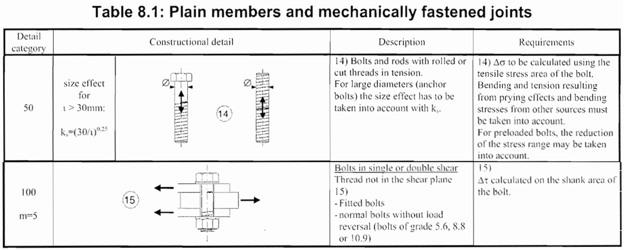
(iii) Stress Diameter
When changing the stress diameter the default “FAT factor” is updated according to Eurocode 3 (Table 8.1) size effect, ks = (30/t)0.25 if the Stress Type is “Normal” or “Structural”.
(iv) FAT Class
The list of FAT Classes can be edited in Bolt Settings using FAT Class Editor.
Use “User defined” to edit S-N curve properties manually (otherwise the properties marked with (*) are in read only mode).
Use “User defined S-N Table” to create a manual S-N Curve using the S-N Table.
Tip: Start typing to filter the list!
(v) Available load steps for fatigue
When evaluating fatigue, the pretension status of each bolt in the group is checked so that bolt results before Load Step Apply is not used (unless pretension force is zero). This since it is un-physical to evaluate the fatigue for the pretension event! The default load type Load Scanning will start at the first available load step time and end at the analysis end time when searching for the max stress range (unless changed by the user). The pretension feature sequential pretension can therefore be used on a bolt group and automatically skip bolts in the scanning util they become preloaded.
S-N Curve
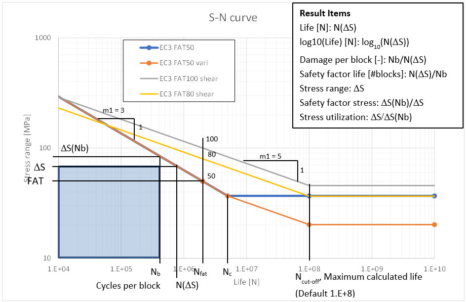
For Normal and Structural stress Eurocode 3 specifies FAT Class “EC3 FAT50” (constant amplitude load) or “EC3 FAT50 vari” (variable amplitude load or cumulative damage).
For Shear stress Eurocode 3 specifies FAT Class “EC3 FAT100 shear”.
Load Types
-
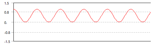
Zero Based (i)
Calculates a pulsating stress range by scaling load step First time with Load scale factor.
-
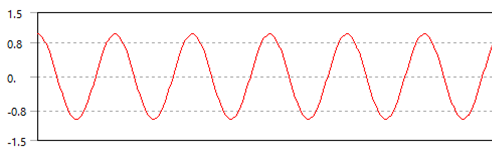
Fully Reversed (i)
Calculates an alternating stress range by scaling load step First time with 2*Load scale factor.
-
Ratio (Loading Ratio) (i) (ii)
Calculates custom stress range defined by scaling load step First time with (1 - Ratio)*Load scale factor.
-
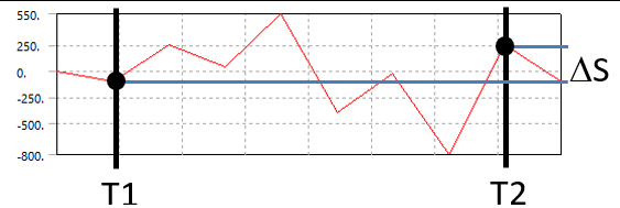
Load Combination
Calculates the stress range between step First time and Last time and scale with Load scale factor.
-
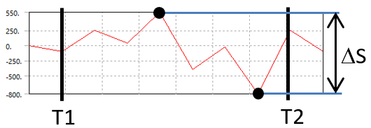
Load Scanning
Calculates the maximum stress range between step First time and Last time and scale with Load scale factor.
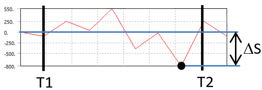
-
Load Scanning (Zero Based) (i) Calculates the maximum stress range from each individual load step between step First time and Last time and scale with Load scale factor.
-
Solution Combination
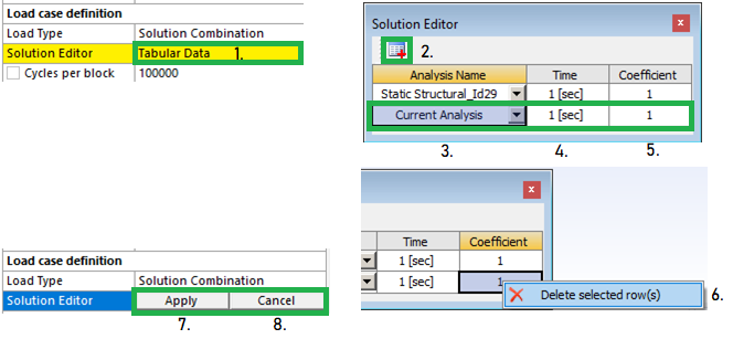
A general load step combination with two or more load steps from any analysis in the model tree. The sum of the steps defines the stress range.- To edit the Solution Editor click on “Tabular Data”
- Click the “Add row” in the table editor
- Select analysis name. (Default “Current Analysis”)
- Define the time step (must be greater than 0)
- Define the load step scaling coefficient (must not be 0)
- To delete a row right-click on a cell and select “Delete selected row(s)”
- Click “Apply” to save the data and close the table editor.
- (Click “Cancel” to close without saving). Do not click the red “Close window” button.
The sum can be scaled with Load scale factor
-
Solution Scanning
Calculates the maximum stress range within all possible combinations of the selected steps in the Solution Editor.
(i) These load types can only be used if Pretension Force Fp is zero.
(ii) Loading Ratio vs. Stress Ratio
The Load Type “Loading Ratio” defines the scaling factors, Kmin & Kmax, from the Ratio for the selected load case, LC, according to the following:
Ratio = Kmin/Kmax , where Kmax = 1.
Range = Kfact·(Kmax·LC – Kmin·LC) = Kfact·(1-Ratio)·LC, where Kfact is the Load scaling factor.If the stress in a bolt for the selected load case is negative, e.g. S = -100, and Ratio = -0.5 the stress range is,
Srange = abs(1·-100 – -0.5·-100) = abs(-100 – 50) = 150
The stress ratio, R = Smin/Smax = -100/50 = -2!
If the stress in a bolt is positive, e.g. S = 100, and Ratio = -0.5, then:
Srange = abs(1·100 – -0.5·100) = abs(100 + 50) = 150, R = 50/100 = 0.5!The “Loading Ratio” will equal the “Stress Ratio” only in bolts where the stress is positive! Defining a load as a “Zero based” or “pulsating” load may in some bolts create stresses with R = 0 and in other bolts R = -inf depending on the stress sign in the load case!
The “Loading Ratio” definition follows Ansys Fatigue Module definition.
Bolt Result
The result items are listed in the table below and are also marked in the “S-N curve” figure above.
When selecting the “Life [N]”, “log10(Life) [N]” or “Safety factor stress” the legend is set to “Reversed Rainbow” and optionally “Logarithmic” and “High Fidelity”. The automatic legend does not modify the legend in the related Figure, but it can be disabled in the Bolt Settings “Automatic Bolt Fatigue Legend = No”.
| Result Item | Description |
|---|---|
| Life [N] | Number of cycles for failure at defined stress range, N(Δσ). |
| log10(Life) [N] | Convenient method to plot the order of magnitude of life, log10(N(Δσ)). |
| Damage per block [-] | Ratio of Cycles per block to calculated Life, D = Nb/N(Δσ). |
| Safety factor life [#blocks] | Number of loading blocks, SFN = 1/D = N(Δσ)/Nb. |
| Stress range | Stress range, Δσ. |
| Safety factor stress | Ratio of allowed stress range to Stress range, SFS = Δσ(Nb)/Δσ. |
| Stress utilization | 1/SFS = Δσ/Δσ(Nb) |
| Stress max | Maximum stress in the fatigue load case. |
| Stress avg | Average (mean) stress in the fatigue load case. |
| Stress min | Minimum stress in the fatigue load case. |
| First time | First of the identified time steps when using “Fatigue Scanning” or “Solution Scanning”. |
| Last time | Last of the identified time steps when using “Fatigue Scanning” or “Solution Scanning”. |
Result Location
The forces and moments are extracted at the mid of the bolt shaft (at the pretension section).
If the Result Location is “Head” or “Thread” the bending moment, Mb, is derived at the corresponding location. (All other section forces are constant along the bolt shaft.)
If the Nominal Diameter Length is greater than zero the Nominal Diameter, d, is used as the Stress Diameter, ds, for “Head” location.
If the Nominal Diameter Length is greater than half the free bolt shaft length the Nominal Diameter, d, is used as the Stress Diameter, ds, for “Mid” location (as in the figure below).
At the “Thread” location the Stress Diameter, ds, is always used.

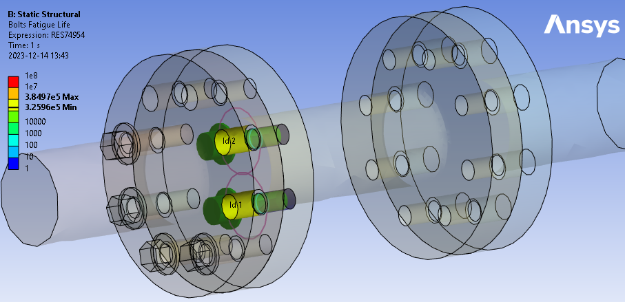
Output
The selected Result Item at the Result Location is displayed on the geometry.
For a Bolt Group Pretension object, the result is displayed on the bolt shaft for each bolt. For a Simplified Bolts or Advanced Bolts the results are presented at the bolt hole (solid parts) or at the bolt head contact (shell parts) for each bolt.
The bolt geometry can be visualized using the Bolt Settings property “Show Bolt Geometry on Results = Yes”.
The Bolts Fatigue object writes a property and result csv files to the solver files directory of the analysis. These files are used by the Bolt Report features and can easily be imported to Word or Excel. You may display the output using the Worksheet Preview feature.
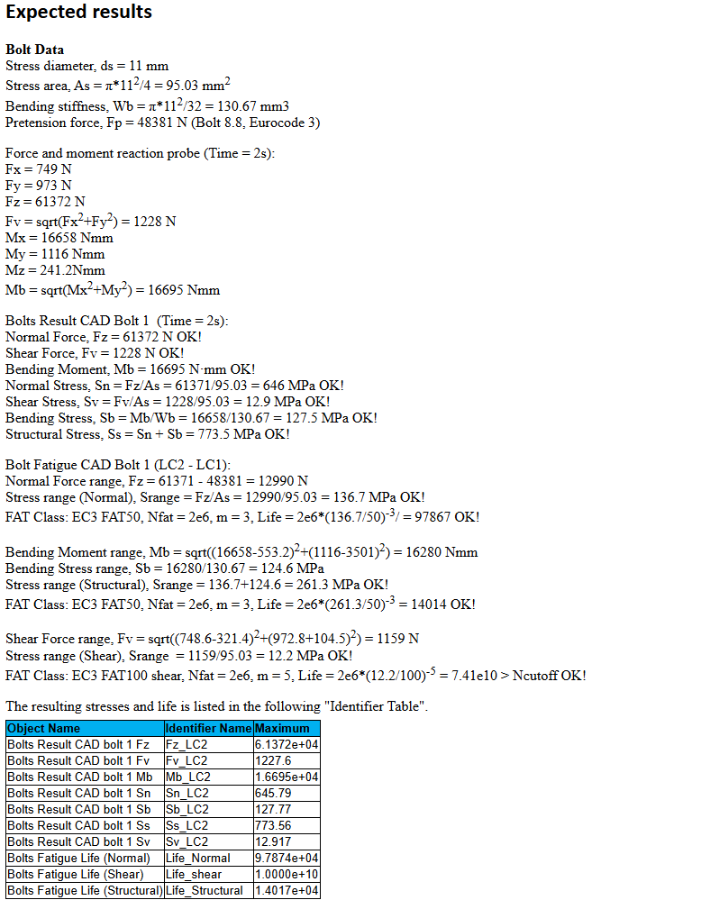
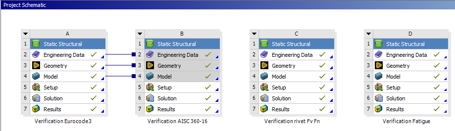
Verification
A fatigue verification model can be downloaded from the “Demo and verification models” found in the Downloads section. A verification report can be automatically created by using the Bolt Report feature. Individual results can be studied using the Worksheet Preview feature.
D: Verification Fatigue
The Bolt Fatigue is tested for Normal, Shear and Structural stress on a “CAD bolt” in a multi-axial loaded flange joint. The results are compared with hand calculations using the force and moment probe results from the bolt shaft. The Bolt Fatigue and Cumulative Damage are also tested for Simplified and Advanced Bolts.
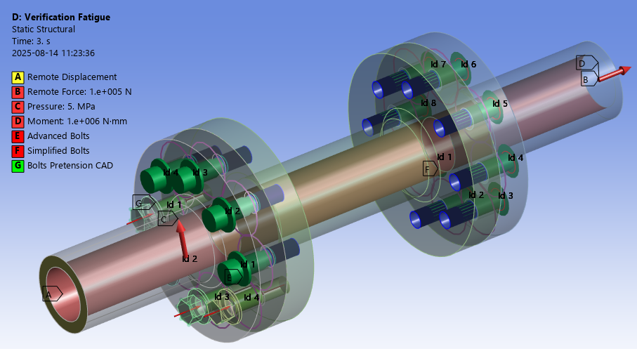
The models show good agreement with hand calculation.