Bolts Strength
Table of contents
About
The “Bolts Result” object adds the post processing features to Bolts Pretension, Simplified Bolts and Advanced Bolts load objects. This result object will extract all relevant information from the selected bolt joint group and create a results summary listing. It also includes the Eurocode 3 evaluation of the bolt results.
Usage
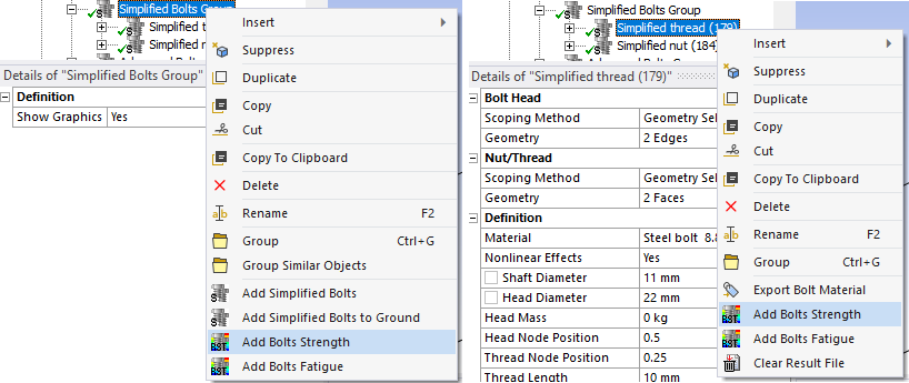
Bolt result objects for all bolts in the Child Setup, Bolts Group or a selected Bolt object can be added using the context action “Add Bolts Strength”.
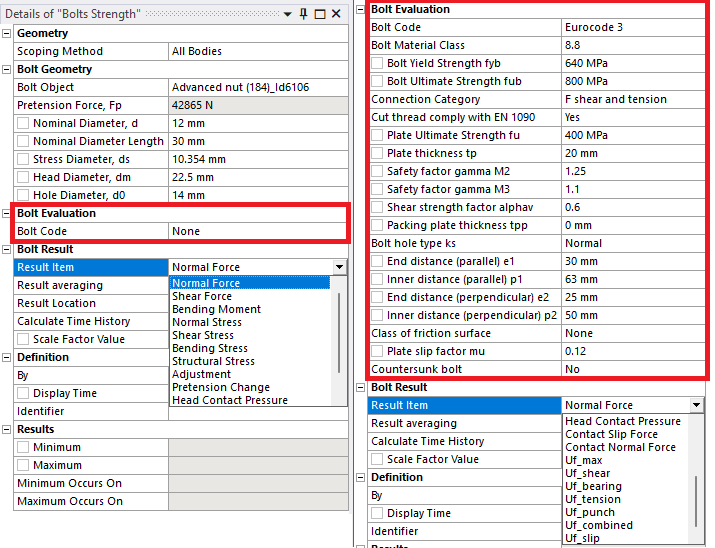
Inputs to define the Bolts Strength are defined in the table below.
If selecting Bolt Code additional properties are visible and described in the Design Codes section.
| Geometry | |
|---|---|
| Scoping Method | All Bodies (Default)/Geometry Selection/Named Selection |
| Geometry | Faces/Bodies to display results on (i). |
| Bolt Geometry | |
| Bolt Object | Select a Bolt object from the list (ii). |
| Pretension Force, Fp | Nominal applied pretension force (read only) |
| Nominal Diameter, d | Shaft nominal diameter used in evaluation (can be changed). |
| Nominal Diameter Length | Length of unthreaded bolt shaft with nominal diameter (can be changed). |
| Stress Diameter, ds | Shaft stress diameter used in evaluation (can be changed). |
| Hole Diameter, d0 | Identified hole diameter (can be changed). |
| Head Diameter, dm | Head diameter (can be changed). |
| Bolt Evaluation | |
| Bolt Code | None/Eurocode 3 (Default)/AISC |
| Bolt Result | |
| Result Item | Select a Result Item to display. |
| Result Tolerance Factor | Value between 0 (Default) to 1 to filter out result values. |
| Result Averaging | Display results for each bolt Individual (Default) or as a Group average. |
| Result Location | Head/Mid (Default)/Thread Location of evaluation section. |
| Calculate Time History | No/Yes/Yes (Maximum Over Time)/Yes (Minimum Over Time) |
| Scale Factor Value | Scale factor on the calculated loads, e.g. load safety factor (iii). |
| Definition | |
| By | Time (Default)/Result Set/Maximum Over Time/Time Of Maximum (standard Mechanical feature) (iv). |
| Display Time | Load step time for results evaluation (v). |
In V2025.23 and later the Analysis Settings/Output Controls is managed automatically by the app when solving the model.
In previous versions the Analysis Settings/Output Controls “Nodal Forces = Yes” must be set in order for post processing to work.
(i) Geometry
To limit post processing to specific bolts in the group edit the geometry scoping of faces or bodies. The node numbers from the selected bolt object will be compared with the node numbers in the selection and results will only be plotted for nodes/bolts that are scooped in the selection.
(ii) Bolt Object
To avoid duplicate names the bolt object Id number is appended to the name. The bolt object may be a Bolts Pretension, Simplified Bolts or Advanced Bolts. When selecting a bolt object the bolt dimensions are retrieved.
(iii) Scale Factor Value
In a Random Vibration analysis this sets the probability of the results (1: 68.269%, 2: 95.45%, 3: 99.73%).
(iv) By
You may use Maximum Over Time to get the worst case from all steps.
In V242.2 the Maximum Over Time (or Minimum Over Time) changes to use the much faster option “Calculate Time History = Yes (Maximum Over Time)”.
(v) Display Time
You may only use time steps where there are results saved, see the graph and tabular data window for load steps to use.
Result Items
The bolt pretension force and geometric dimensions are used in the code evaluation.
| Result Item | Description |
|---|---|
| Normal Force | Axial force in bolt shaft, Fn (i) |
| Shear Force | Shear force sum in bolt shaft, Fv |
| Bending Moment | Bending moment sum in bolt shaft, Mb |
| Normal Stress | Axial stress in bolts shaft, σn = Fn/As where As = πd2/4 |
| Shear Stress | Shear stress in bolt shaft, τv = Fv/As |
| Bending Stress | Bending stress in bolt shaft, σb = Mb/Ws where Ws = πd3/32 |
| Structural Stress | Normal + Bending stress in a bolt shaft, σs = σn + σb |
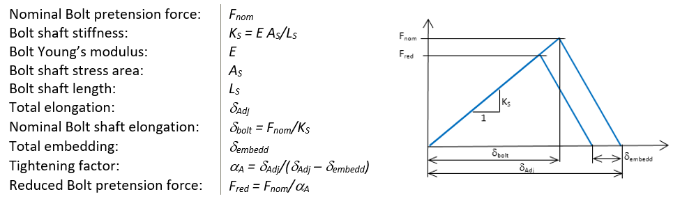
| Adjustment | Total elongation of bolt joint (displacement of pretension element) δAdj |
| Pretension change | Change of axial force relative to pretension force, Fdiff = Fn - Fp |
| Head Contact Pressure | Average head contact pressure, Phead = Ft/Anet where Anet = π(dm2-d02)/4 (ii) |
| Contact Slip Force | Average contact shear force per contact plane, FsEd |
| Contact Normal Force | Average contact normal force per contact plane, FcEd |
(i) Normal Force
If using Pretension Type “MPC184” the Normal Force at the “Load Step Apply” will not be listed or plotted in the bolt result. When extracting results for MPC184 the joint constraint forces are used in order to get forces in the bolt local system. Therefore the normal force will only be visible in listing and plotting at the “Load Step Lock” or later. MPC184 should only be used when large deflections or rotations are present in the model.
(ii) Tension Force
The Tension Force used in Head Contact Pressure is the positive part of Normal Force, Ft = max(0, Fn).
Result Location
The forces and moments are extracted at the mid of the bolt shaft (at the pretension section).
If the Result Location is “Head” or “Thread” the bending moment, Mb, is derived at the corresponding location. (All other section forces are constant along the bolt shaft.)
For Advanced Bolts this impacts the stress calculation for “Normal Stress”, “Shear Stress”, “Bending Stress” and “Structural Stress”.
If the Nominal Diameter Length is greater than zero the Nominal Diameter, d, is used as the Stress Diameter, ds, for “Head” location.
If the Nominal Diameter Length is greater than half the free bolt shaft length the Nominal Diameter, d, is used as the Stress Diameter, ds, for “Mid” location (as in the figure below).
At the “Thread” location the Stress Diameter, ds, is always used.

All tension force related design strength criteria uses the Stress Diameter at the thread, i.e. Design Preload “FpCd” and Design Tension resistance “FtRd” in order to be conservative. The resulting bolt utilizations “Uf_tension”, “Uf_pretension” and “Uf_combined” is therefor also always evaluated conservative independent of the Result Location.
Output
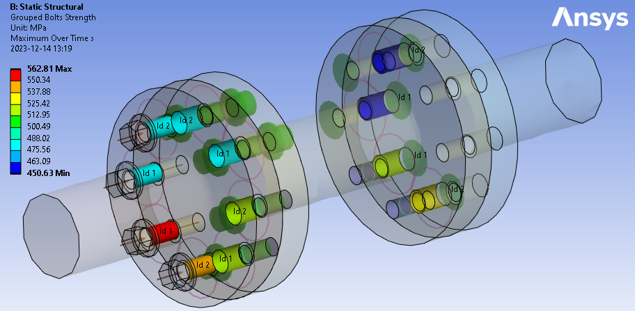
The selected “Result Item” at the Result Location is displayed on the geometry.
For a Bolt Group Pretension object, the result is displayed on the bolt shaft for each bolt.
For a Simplified Bolts or Advanced Bolts the results are presented at the bolt hole (solid parts) or at the bolt head contact (shell parts) for each bolt.
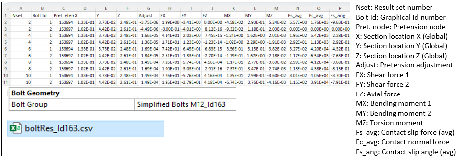
The Bolts Result object writes a property and result csv files to the solver files directory of the analysis. These files are used by the Bolt Report features and can easily be imported to Word or Excel.
You may display the output using the Worksheet Preview feature. If Result Averaging = “Group” is selected the group average is listed on the first line with Bolt Id = “0”. The Group average is useful for post processing e.g. the risk for global slipping in a bolt group, i.e. the average slip utilization of all bolts is greater than 1.
Graphics
The bolt geometry can be visualized on the results using the Bolt Group Setting property “Show Geometry on Results = Yes”. The translucency can also be set for the results using the property “Result Translucency”.
If the Result Item is “Shear Force”, “Bending Moment” or “Contact Slip Force” a vector is displayed at the bolt shaft mid when selecting an evaluated result.
The reaction force vector direction relates to the bolt head part or the first contact side part (if there are multiple contacts in the joint). The length of the vector is proportional to the individual magnitude of the force. For “Grouped results” or “Maximum over Time” no vector is displayed.

Derived bolt results
From the results listing additional bolt joint post processing can be done, e.g. to study embedding influence on bolt pretension or the relation in stiffness between bolt shaft and support.
Output csv files
When post processing a bolt group for the first time the bolt index, coordinates, section forces and moments are extracted for all load steps and written to csv file in the sub folder “BoltToolkit” in the solver files directory (in the solution units). This file is used when post processing the bolts.
The bolt coordinate system can be displayed in the graphics using the Bolt Settings option “Show Bolt Coordinate System = Yes”.
The contact slip and normal force is dependent on the Contact Slip Radius.
Contact slip and normal force
The average slip and normal force per contact plane is derived from contact pairs along the bolt shaft within the “contact slip radius”, rslip, the first time the bolt group is post processed. The radius is defined in the parent bolt group object and plotted as a purple circle at the bolt shaft mid.
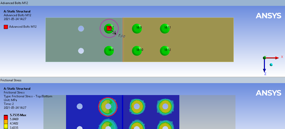
For the slip evaluation to work the bolts must have pretension and the contacts must be frictional so that the contact friction stress is concentrated around the bolts as in the figure above.
Use contact behavior “Asymmetric” instead of “Program Controlled” (auto asymmetric) to speed up post processing. Otherwise, there is an extra deactivated contact pair with zero result for every active pair.
Bonded contacts may be used only if creating imprints in the contact faces around each bolt and exclude the areas outside the imprint from the contact.
Before evaluating the bolt result verify that the Contact Slip Radius circles do not overlap each other. The resulting contact force extraction will then be erroneous since a to large area is included when summing the force around each bolt (left figure below). Reduce the Contact Slip radius until they just touch before evaluating.
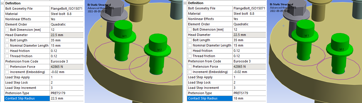
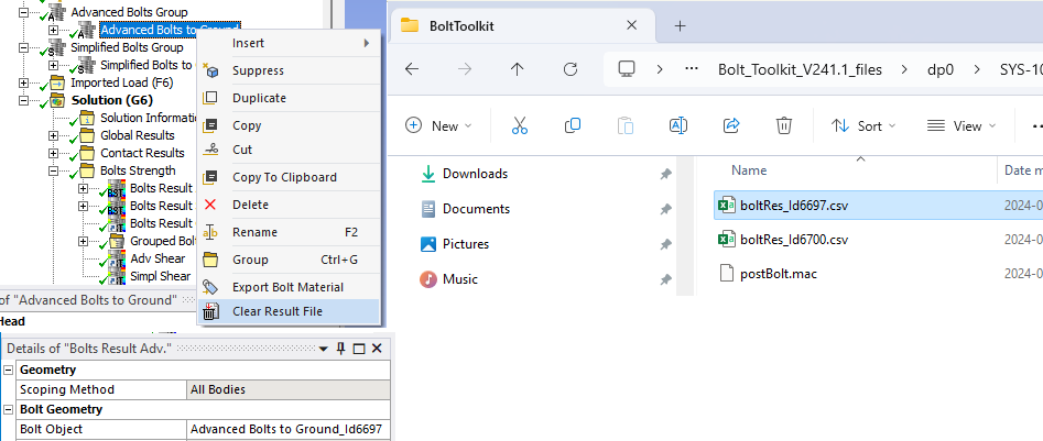
When the model is solved the Contact Slip radius can be changed without needing to re-solve the analysis but the cached bolt result file must be deleted manually. Right-click on the corresponding Bolt object and select the action “Clear Result File”. Clear the bolt result and evaluate it again. (The “boltRes” file is re-generated.)
Verification
A strength verification model can be downloaded from the “Demo and verification models” found in the Downloads section. A verification report can be automatically created by using the Bolt Report feature. Individual results can be studied using the Worksheet Preview feature.
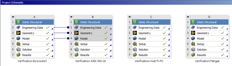
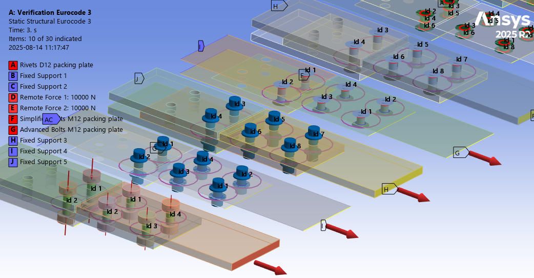
A/B: Verification Eurocode3 & AISC 360-16
The Bolt Strength utilization according to Eurocode 3 and AISC 360-16 is tested for both solid and shell plates with and without a “packing plate” for all bolt types. The models are tested for pure shear loading. The hand calculation is found in the Mechanical model as a “Comment” for each result.
The Eurocode 3 model show good agreement with hand calculation.
Uf,max = 0.884
Uf,shear = 0.090 (packing plate)
Uf,shear = 0.077 (no packing plate)
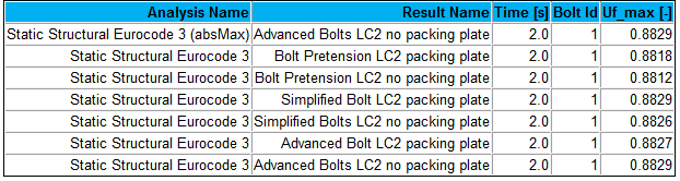
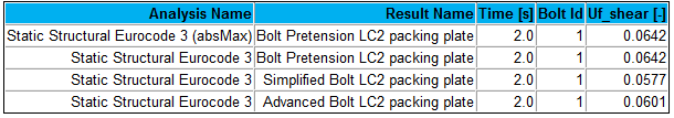
The shear utilization assumes that all shear force is acting on the bolt shaft (and nothing in the frictional contact). In the FE-model the shear load is distributed on both the bolt shafts and contact.
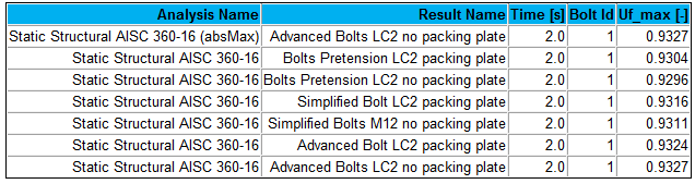
The AISC 360-16 model show good agreement with hand calculation.
Uf,max = 0.933