 Rivets
Table of contents
About
The Rivets is a load feature where so called “Rivets” are created and placed in a group folder in the current structural (or thermal) analysis. The Rivet is constructed of BEAM188 solid circular beam element for the rivet shaft and a MPC CERIG or RBE3 remote points for the heads and intermediate sections.
New in 2025 R1 is that any matching “Remote Point” will be used. This will allow for more advanced usage combining connections and rivets as well as Condensed parts.
In thermal analysis LINK33 is used. This is the similar as the standard “Beam connection” except that rivet creates one beam element for each layer in the connected assembly. The additional features with the Rivets compared to “Beam connection” are that:
- Multiple rivets can be defined in one load object, i.e. all D12 rivets of the model.
- A point mass (MASS21 element) can be added to the rivet head to account for missing mass.
- All rivets are saved in one place, the “Rivets Group” folder.
- The rivets can have different orientation.
- Thermal loads on the bodies will be mapped to the rivets to account for correct thermal elongation.
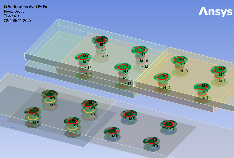
- Post processing of the Rivets is done using the Rivets Strength object.
Usage
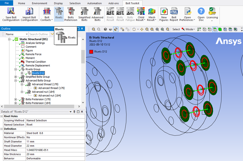
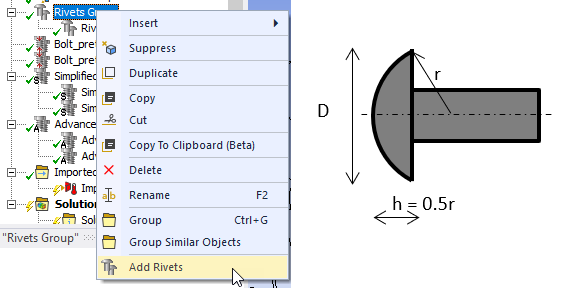
Click on “Rivets” in the toolbar to insert the Rivets Group folder in the current static analysis as well as creating the first Rivets load object. To add additional rivets, right click on the Rivets Group folder and select “Add Rivets” or click on “Rivets” in the toolbar. You can also use “Duplicate” on an existing Rivets and modify the properties.
You can add multiple “Rivets Groups” using the context action “Insert>Rivets Group” on the the selected “Analysis”.
Inputs to define the rivets are:
| Rivet Holes | |
|---|---|
| Scoping Method | Geometry Selection/Named Selection (i) |
| Geometry | Vertices/Edges/Faces/Bodies/Nodes (ii) |
| Rivet Geometry | |
| Shaft Diameter, d | Rivet diameter that defines the circular solid section for the beam element. |
| Hole Diameter (min) | Sets the hole search min diameter if using “face/body selection”. |
| Hole Diameter (max), d0 | Sets the hole search max diameter if using “face/body selection” and is also used as the hole diameter in Rivet Strength results. |
| Head Diameter, dm | Sets the maximum size of the rivet head MPC. By default two times the shaft diameter is used. |
| Min thickness | Search distance for creating rivets, i.e. minimum rivet shaft section length. |
| Max thickness | Search distance for creating rivets, i.e. maximum rivet shaft section length. |
| Coincident tolerance factor | > 0 (Default 0.1) Tolerance factor on “Shaft Diameter” for coincident rivet holes. |
| Face angle tolerance | 0 <= 5 (Default) < 90 degree. Face normal angle tolerance. |
| Rivet Properties | |
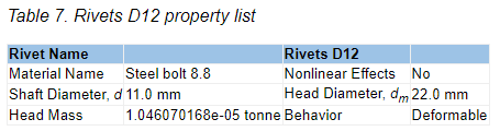
| Material | Select material from “Engineering Data” or App default materials. |
| Nonlinear Effects | No (Default)/Yes. Use plasticity models defined in the selected material (iii) |
| Head Mass | Add the missing mass (optional). Default calculated to the mass of a sphere section based on steel density. The sphere section diameter, D, is the “Head Diameter” and the sphere section height, h, is D/(2√3), see the figure above. |
| Behavior | Rigid/Deformable/Beam/Custom. |
| Symmetry BC | No (Default)/Auto. Identify symmetry plane rivets. |
| Definition | |
| Attribute | Select an “Attribute” to filter out holes and define the properties of the rivets. Visible only if an Attribute File has been selected for the group. |
| Pinball Factor | 1 (Default) Factor for scaling the pinball radius used to filter out holes of the rivets. Visible only if an “Attribute File” has been selected. |
| Rivet Count | Number of rivet segments created. (Read only) |
(i) Scoping Method
The manual “Geometry Selection” can be converted to a “Named Selection” using the context action “Promote to Named Selection”.
(ii) Geometry
Vertices on shell bodies and edges on shell and solid bodies are supported. If selecting faces/bodies the range of Hole Diameter (min), and Hole Diameter (max), d0 is used to search for holes defined by at least one circular edge section.
Half circles and cylinders at symmetry planes can be selected.
The face/body selection can be converted to edge selection using the context action “Convert to Edge Selection”.
Nodes from a Condensed Part can be selected.
(iii) Material
The following material properties (and corresponding MAPDL MP Lab) are supported: Young’s Modulus (EX), Poisson’s Ratio (NUXY), Density (DENS), Coefficient of Thermal Expansion (ALPX), Thermal Conductivity, (KXX), Specific Heat (C), Isotropic Hardening (BISO & MISO), Kinematic Hardening (BKIN, KINH). If orthotropic properties are defined the X component is automatically used (EX, NUXY, ALPX & KXX).
Graphics
A graphic representation is created once valid inputs are given. At least two sets of hole edges are needed to make a valid selection. The Rivets load object connect holes fulfilling the following criteria:
- The normal distance is in the range of Min thickness to Maximum thickness.
- The angle between the face normals is less than Face angle tolerance.
- The planar offset between the hole centroids is less than 10% of the Shaft Diameter.
Hole centroids with a distance offset less than 10% (Rivet coincident tolerance factor) of the Shaft Diameter are made coincident and aligned with the smaller hole. The default values for “Rivet coincident tolerance factor” and “Face angle tolerance” can be edited in the Bolt Settings object.
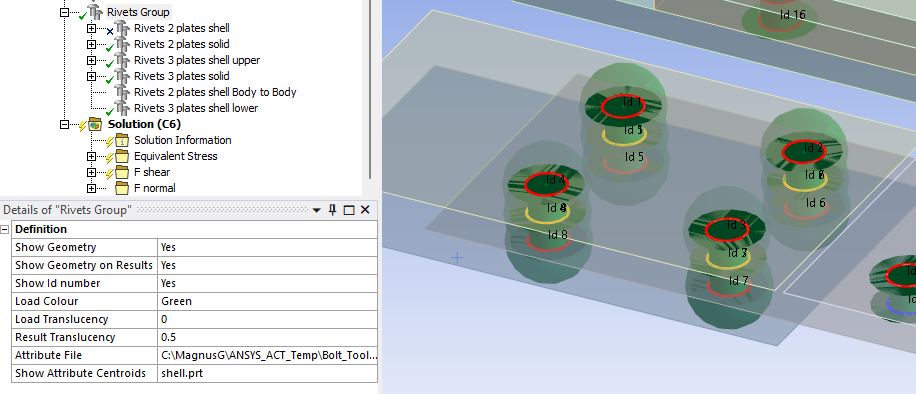
The head diameter is plotted as a disc normal to the rivet shaft (if Head Diameter > Hole Diameter) and the rivet shaft as a cylinder. The active Rivet Holes or Rivet Source edges are plotted in thick red lines. The active Rivet Target edges are plotted in thick blue lines (for Body to Body rivets). Edges shared between two different rivet objects are plotted in thick orange lines.
Un connected hole edges are plotted in thin red lines. The rivet section Id number is printed at the center of each connected edge and is used in the result tables. The colour, translucency and printing of “Id” numbers is defined in the Rivets Group object. The display of all rivets in the Rivets Group can be disabled by setting “Show Graphics = No”. The default values for the group can be defined in the Bolt Settings.
A property file is also written to the solver files directory that is used by the Bolt Report feature.
Rivets Body to Body
The Rivets Body to Body is a variant of Rivets that uses two scoping groups (Rivet Source and Rivet Target) and will only create rivets connecting holes between the two groups.
This is useful for defining connections to assemble different components when using “Model assembly” on the project page to avoid creating new connections within the individual components.
Right click on the Rivets Group folder and select “Add Rivets Body to Body”.
Create Washer Mesh
A “Washer” mesh imprint around the rivet holes can be added using the context action “Create Washer Mesh” for an individual rivet object or on the Rivets Group.
If updating the scoping for the rivet you may use “Create Washer Mesh” again to apply the changes.
The created mesh object may be edited if needed, e.g. to change the “Number of Divisions” or “Number of Washer Layers”. For shell parts a “Quad Layer” is used and for solid parts “Sizing”, “Face Meshing” and “Inflation” objects are used.
To delete the mesh object use the context action “Delete Washer Mesh” (or delete individual objects in the model tree).
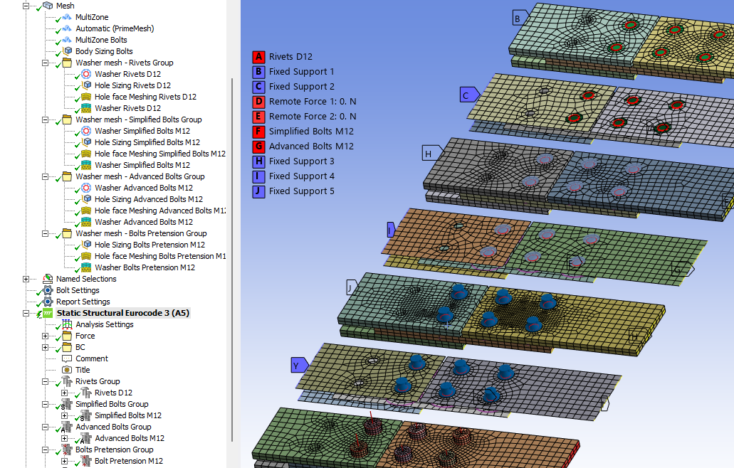
Set the Mesh>Automatic Method “Sheet Body Method = PrimeMesh” or assign the mesh “Method = Automatic (PrimeMesh)” to the shell parts.
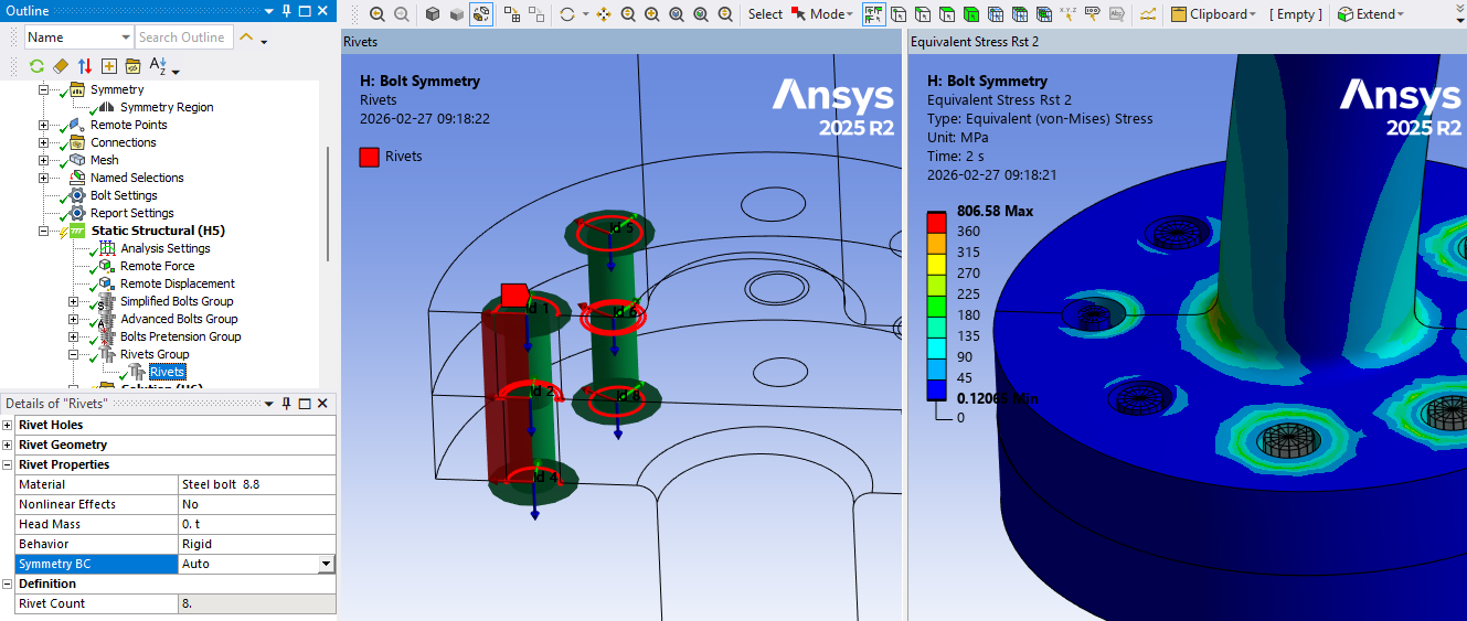
Symmetry BC
Using “Symmetry BC = Auto” will identify all rivets with a single half circle edge at the rivet head as symmetry rivets. Using “Symmetry BC = Yes” will identify all rivets in the group that has a half circle or slotted hole as symmetry rivets. The graphics will mark symmetry rivets with a red plane along the rivet shaft. A symmetry rivet is meshed with beam elements with half the stress area the cut plane nodes are constrained in the normal direction as well as for out-of-plane rotations.
Condensed Part
The Condensed Parts can be defined in two different ways, “Top down” and “Bottom up”.
- Top down workflow: Insert a “Condensed Geometry” object in the model tree and select parts to be condensed (and exported).
The condensed part(s) are automatically part of all analyses in the model tree.
The condensed part results can be expanded but Bolt Toolkit results will not be able to evaluate. - Bottom up workflow: Insert a “Substructure Generation” system to the project or the model tree to condense an entire model.
The model is then exported as a “CPA” part and imported in a different analysis using the “Imported Condensed Part” from the “Condensed Geometry” object.
When exporting the CPA in 2025 R1 or newer you may select to include files needed for expanding the results and this creates a very large file.
Always export the CPA without expansion.
Only export the CPA with expansion if planning to evaluate results on the CPA part.
See the Ansys Mechanical help section 5.15.14 Substructure Analysis
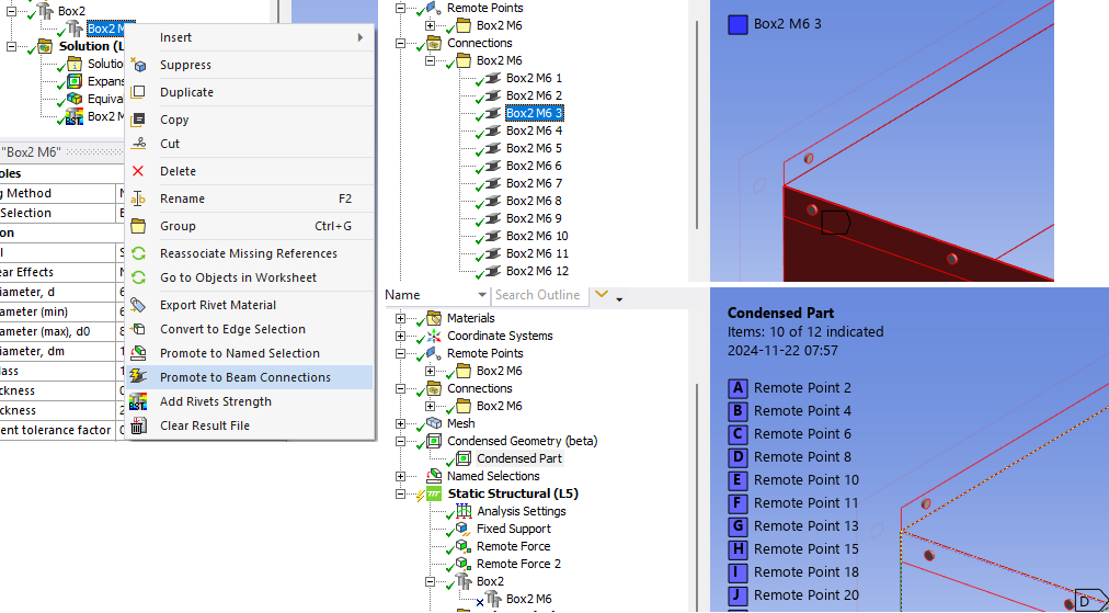
Condensed Geometry
Inserting a “Condensed Geometry” and “Condensed Part” in the model tree requires that any rivets or bolts connected to the selected bodies must be converted to Beam Connections using the Promote to Beam Connections action.
This conversion will then allow you to select any of the rivets or bolts Remote Points as interface for the Condensed Part. The Condensed Part can then be used in the down stream analysis using other rivets or simplified bolts to connect the bodies. Use the normal “Geometry Scoping” to identify the holes (and corresponding remote points).
Substructure Generation
In a “Substructure Generation” system you may use rivets or bolts to connect parts just as in a static analysis.
To include bolt pretension you must define the bolt pretension and contacts in a static system and select this as the “Pre-Stress” system in the Substructure system (similar as pre-stressed modal analysis).
Exporting Condensed Part (CPA)
When exporting the Condensed Part (as a “.cpa” file) and importing into a different analysis system you must use “Nodal Scoping” to identify the holes to create the connection between the parts. Use e.g. the Rivets Body to Body to select nodes on one side and geometry on the other.
Promote to Beam Connections
A defined rivet object or the entire rivet group can be promoted to Mechanical “Beam Connections” including the needed “Remote Points”.
Right click on the rivet object and select the context action “Promote to Beam Connections”.
 The beams are grouped into a folder with the same name as the rivet object as well as the related remote points.
When the beams has been exported the rivet object is automatically suppressed.
When un-suppressing the rivet object the corresponding beam connections are suppressed (but the remote points remains).
Group Features
The Group object is used to collect and organize the individual types of joints (Rivets/Pretension/Simplified Bolts/Advanced Bolts). It is possible to insert more than one Group object using the context action “Insert>Rivets Group” on the selected “Analysis”.
| Definition | |
|---|---|
| Show Geometry | Yes (Default)/No Enable Group view of all group children. (i) |
| Show Geometry on Results | Yes (Default)/No Plot Rivet/Bolt geometry on results. |
| Show Id number | Yes (Default)/No Plot Id number on Rivet/Bolt head. |
| Show Coordinate System | Yes/No (Default) Plot Rivet/Bolt coordinate system at shaft mid. |
| Load Colour | Colour of Rivet/Bolt geometry. |
| Load Translucency | (Default 0.0) Translucency of Rivet/Bolt objects (0: Solid, 1: Transparent) |
| Result Translucency | (Default 0.7) Translucency of Rivet/Bolt objects in results. |
| Bolt Configuration Source | None (Default) Click to select a Bolt Configuration Source file. |
| Attribute File | None (Default) Click to select an Attribute File. |
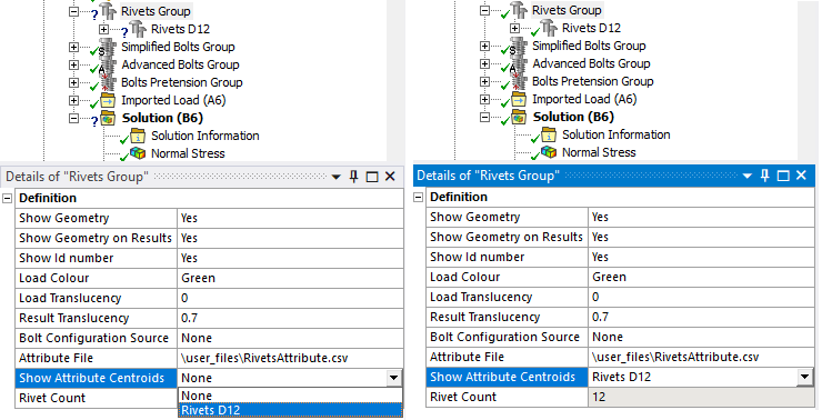
| Show Attribute Centroids | None (Default) Select an attribute to display the centroid points. |
| Rivet/Bolt Count | Number of rivet segments or bolts in the group. (Read only) |
(i) The graphics of all Rivet/Bolt geometry is cashed in memory to speed up the show/hide of objects. When hiding a bolt object it will not clear graphics for other apps or Mechanical scripts. If the graphics gets “stuck” you can set the General Settings - Show Geometry to “No” to clear all >graphics and then set it to “Yes” again.
Load Colour
The colour of the Rivet/Bolt geometry can be set for each group individual. This is useful if using several groups of Rivets/Bolts for different parts or sub-assemblies of the model.
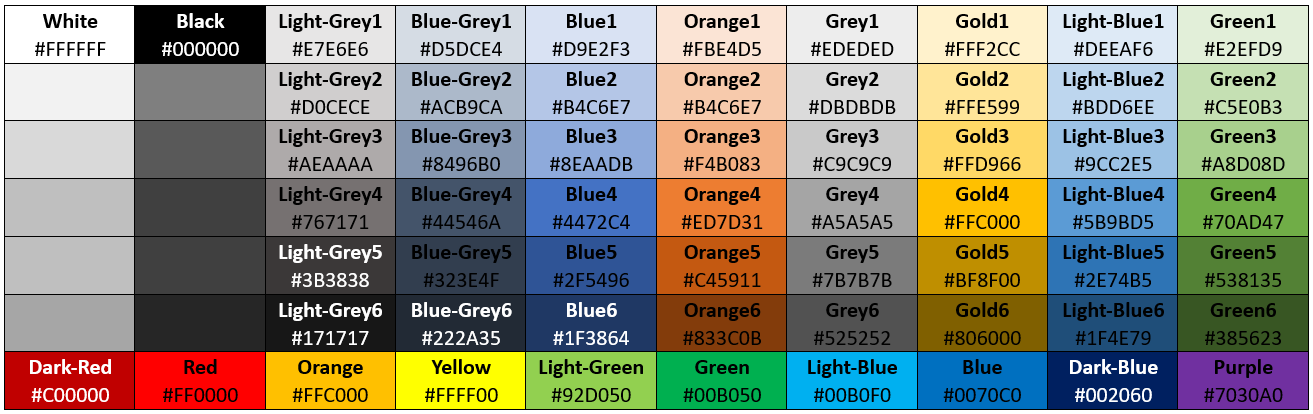
The available colours can be edited in General Settings - Load Colours Table.
Bolt Configuration Source
This property is hidden by default but is useful if using “Model Assembly” to combine models.
When Importing a Bolt Configuration to the Analysis this property becomes visible and file name is displayed. If the source configuration file is updated the changes can be applied by the context action “Update Group from Source”.
- The group name must be unique and match one name in the source file of the same type, otherwise nothing is updated.
- An existing child in the group is updated if the child name is unique and matches one child in the source file.
- Additional children from the source file are added if they are missing in the group.
- Existing children that are not in the source file are left unchanged.
The property visibility can be toggled by the context action “Reset Attribute File”.
When hiding the property the source file name is reset to “None”.
When an analysis is solved the Save Bolt Configuration is executed.
Attribute File
An “Attribute file” property can be enabled for the Rivets/Bolts Group by using the context action “Reset Attribute File” to toggle the property visibility.
The attribute file is a csv file containing a list of rivet coordinates and optional properties to define the rivet, see example below.
When selecting an Attribute File a Rivet/Bolt object will be created for each “Attribute” in the file if unused in the group. If selecting an “attribute” name for the Rivet/Bolt object the holes will be filtered to match the coordinates in the file. The Hole Diameter multiplied by the Pinball factor is used as the search pinball radius when filtering the holes. The Show Attribute Centroids is used to select an Attribute to display the coordinate points and also the resulting pinball sphere if the attribute is used in any rivet object.
The properties, Caption, objectName, rivetHoles, rivetTarget, material, nonlinear, shaftDiameter, minDiameter, holeDiameter, headDiameter, addMass, minThickness, maxThickness, rivetCoincidentTol, rivetAngleTol, behavior and pinBallFactor can also be defined. The coordinates, (X, Y, Z) may be left blank to avoid filtering the holes. The scoping properties (rivetHoles, rivetTarget) defines the Named Selection to use.
When opening a project that uses the Attribute (or Bolt Configuration Source) feature a “?” may appear on the Group and its children and the Solution.
To remove the “?” toggle e.g. the “Show Id number” or “Show Attribute Centroids” to avoid invalidate the solution.
The template attribute file below can be copied by clicking in the upper right corner of the code window.
// RivetAttributes.csv
attribute,Id,X [mm],Y [mm],Z [mm],Caption,objectName,rivetHoles,rivetTarget,material,nonlinear,shaftDiameter [mm],minDiameter [mm],holeDiameter [mm],headDiameter [mm],addMass [kg],minThickness [mm],maxThickness [mm],rivetCoincidentTol,rivetAngleTol [deg],behavior,pinBallFactor
solid.prt, 1,30.,30.,-75.,Rivets 3 plates solid,rivetConnections,solid bodies,,Steel bolt  5.8,No,12.0,11.0,13.0,24.0,,0.0,10.0,,,Rigid,1.0
solid.prt, 2,30.,10.,-75.,Rivets 3 plates solid,rivetConnections,solid bodies,,Steel bolt  5.8,No,12.0,11.0,13.0,24.0,,0.0,10.0,,,Rigid,1.0
solid.prt, 3,30.,20.,-75.,Rivets 3 plates solid,rivetConnections,solid bodies,,Steel bolt  5.8,No,12.0,11.0,13.0,24.0,,0.0,10.0,,,Rigid,1.0
solid.prt, 4,30.,0.0, 75.,Rivets 3 plates solid,rivetConnections,solid bodies,,Steel bolt  5.8,No,12.0,11.0,13.0,24.0,,0.0,10.0,,,Rigid,1.0