 Design Codes
Table of contents
 General Information
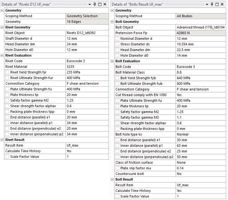
The Eurocode 3 and AISC 360-16 implementation has been reworked and the interface in Rivets/Bolts Result is updated in the 2021R1 release. When selecting “Eurocode 3” (or “AISC 360-16”) in the “Code” field additional properties are displayed.
Rivet/Bolt Geometry
When selecting a Rivet or Bolt object the dimensions for the selected object are retrieved and the values are displayed in the Rivet/Bolt Geometry group. The dimensions are used in the evaluation and can be adjusted without re-solving the model.
The used Engineering Data material name of the selected Rivet or Bolt is matched with the Rivet/Bolt Material Class.
Rivet/Bolt Evaluation Properties
Depending on selected “Connection Category” only the relevant properties are displayed.
| Rivet Evaluation | |
|---|---|
| Rivet Code | None/Eurocode 3 (Default) |
| Rivet Material Class | Select material class. (Sets fyr, fur, αv and γM2) (Default “S235”) |
| Rivet Yield Strength, fyr | fyr > 0 (Default 640 MPa) |
| Rivet Ultimate Strength, fur | fur > 0 (Default 800 MPa) |
| Connection Category | Select rivet connection category from selected Rivet Code (Default “F shear and tension”) |
| Plate Ultimate Strength, fu | fu > 0 (Default 400 MPa) Connected part ultimate strength |
| Plate thickness, tp | tp > 0 (Default 0 mm) Connected part thickness |
| Safety factor, gammaM2 | γM2 > 0 (Default 1.25) |
| Shear strength factor, alphav | αv > 0 (Default 0.6) |
| Packing plate thickness, tpp | tpp ≥ 0 (Default 0 mm) |
| End distance (parallel), e1 | e1 ≥ spacing(e1) > 0 (Default 0 mm) |
| Inner distance (parallel), p1 | p1 ≥ spacing(p1) > 0 (Default 0 mm) |
| End distance (perpendicular), e2 | e2 ≥ spacing(e2) > 0 (Default 0 mm) |
| Inner distance (perpendicular), p2 | p2 ≥ spacing(p2) > 0 (Default 0 mm) |
| Bolt Evaluation | |
|---|---|
| Bolt Code | None/Eurocode 3 (Default)/AISC 360-16 |
| Bolt Material Class | Select material class. (Sets fyb, fub, αv and γM2) (Default “8.8”) |
| Bolt Yield Strength, fyb | fyb > 0 (Default 640 MPa) |
| Bolt Ultimate Strength, fub | fub > 0 (Default 800 MPa) |
| Connection Category | Select bolt connection category from selected Bolt Code (Default “E preloaded”) |
| Cut thread comply with EN 1090 | No/Yes (Default) |
| Plate Ultimate Strength, fu | fu > 0 (Default 400 MPa) Connected part ultimate strength |
| Plate thickness, tp | tp > 0 (Default 0 mm) Connected part thickness |
| Safety factor, gammaM2 | γM2 > 0 (Default 1.25) |
| Safety factor, gammaM3 | γM3 > 0 (Default 1.25) |
| Shear strength factor, alphav | αv > 0 (Default 0.6) |
| Packing plate thickness, tpp | tpp ≥ 0 (Default 0 mm) |
| Bolt hole type, ks kb kb | Normal (Default)/Oversized/Slotted (perpendicular)/Slotted (parallel)/Long Slotted (perpendicular)/Long Slotted (parallel) |
| End distance (parallel), e1 | e1 ≥ spacing(e1) > 0 (Default 0 mm) |
| Inner distance (parallel), p1 | p1 ≥ spacing(p1) > 0 (Default 0 mm) |
| End distance (perpendicular), e2 | e2 ≥ spacing(e2) > 0 (Default 0 mm) |
| Inner distance (perpendicular), p2 | p2 ≥ spacing(p2) > 0 (Default 0 mm) |
| Class of friction surface | muClass (Default “None”) |
| Plate slip factor, mu | μ > 0 (Default = 0.12) |
| Countersunk bolt faktor, k2 | No (Default)/Yes |
Plate thickness, tp
When selecting a rivet/bolt object the Plate thickness, tp is derived from the shell or solid body at the first bolt head.
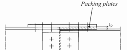
Packing plate thickness, tpp
If “Packing plates” (spacers) are used tpp should be defined as the thickness of the thicker packing.
Spacing
The values for end and inner distance are checked according to the function “spacing” in the preference file.
When selecting a rivet/bolt object the default minimum allowed spacing is derived based on the Nominal Diameter, d or Hole Diameter, d0 for the current selected Code if the spacing values are zero.

 Eurocode 3
Reference to sections and equations from Eurocode 3 are shown in brackets or italics.
Cut thread comply with EN 1090
Global resistance factor ktv. Yes: 1.0, No: 0.85 (Section 3.6.1)(3)
Packing plate thickness, tpp
Thickness to calculate reduction in shear resistance (Section 3.6.1)(12)
Countersunk bolt factor, k2
Tension resistance factor No: 0.9, Yes: 0.63 (Section 3.9.1)
Material Grade
The Material Grade is defined in the Material Grade for each design code.
The values are from: “Table 3.1: Nominal values of the yield strength fyb and the ultimate tensile strength fub for bolts”.
Shear strength factor, αv, (Table 3.4).
Joint resistance partial safety factor, γM2, (Table 2.1).
Slip resistance partial safety factor, γM3, (Table 2.1).
| Material Grade (Bolt) | fyb [MPa] | fub [MPa] | αv | γM2 |
|---|---|---|---|---|
| 3.6 | 180 | 300 | 0.60 | 1.25 |
| 4.6 | 240 | 400 | 0.60 | 1.25 |
| 4.8 | 320 | 400 | 0.50 | 1.25 |
| 5.6 | 300 | 500 | 0.60 | 1.25 |
| 5.8 | 400 | 500 | 0.50 | 1.25 |
| 6.8 | 480 | 600 | 0.50 | 1.25 |
| 8.8 | 640 | 800 | 0.60 | 1.25 |
| 9.8 | 720 | 900 | 0.50 | 1.25 |
| 10.9 | 900 | 1000 | 0.50 | 1.25 |
| 12.9 | 1000 | 1200 | 0.50 | 1.25 |
| 14.9 | 1260 | 1400 | 0.50 | 1.25 |
| 4.8 partially threaded | 320 | 400 | 0.60 | 1.25 |
| 5.8 partially threaded | 400 | 500 | 0.60 | 1.25 |
| 6.8 partially threaded | 480 | 600 | 0.60 | 1.25 |
| 9.8 partially threaded | 720 | 900 | 0.60 | 1.25 |
| 10.9 partially threaded | 900 | 1000 | 0.60 | 1.25 |
| 12.9 partially threaded | 1080 | 1200 | 0.60 | 1.25 |
| 14.9 partially threaded | 1260 | 1400 | 0.60 | 1.25 |
| Material Grade (Rivet) | fyr [MPa] | fur [MPa] | αv | γM2 |
|---|---|---|---|---|
| S235 | 235 | 400 | 0.60 | 1.25 |
| S275 | 275 | 410 | 0.60 | 1.25 |
| S355 | 355 | 470 | 0.50 | 1.25 |
| S420 | 420 | 520 | 0.60 | 1.25 |
| S460 | 460 | 540 | 0.50 | 1.25 |
The result “Scale Factor Value” γL is not defined in the tables and must be defined manual.
Connection Category
| Connection Category (Section 3.4) | Notes |
|---|---|
| Shear connections (Section 3.4.1) | Bolted connections loaded in shear should be designed as one of the following |
| A bearing | No preload required. Bolt classes from 4.6 to 10.9 may be used. |
| B slip-resistant at serviceability | Preloaded 8.8 or 10.9 bolts should be used. |
| C slip-resistant at ultimate | Preloaded 8.8 or 10.9 bolts should be used. Note: Base material resistance Nnet.Rd is not included! |
| Tension connections (Section 3.4.2) | Bolted connections loaded in tension should be designed as one of the following |
| D non-preloaded | No preload required. Bolt classes from 4.6 to 10.9 may be used |
| E preloaded | Bolt class is checked to be 8.8, 9.8, 10.9 or fub >= 800 MPa (Section 3.1.2) |
| Shear and Tension connections | Bolted connections loaded in shear and tension (note in Table 3.2) |
| F shear and tension | Bolts should also satisfy the criteria given in Table 3.4 |
Bolt hole type
| Bolt hole type (Table 3.6) | Slip factor ks | Bearing factor kb |
|---|---|---|
| Normal | 1.00 | 1.00 |
| Oversized | 0.85 | 0.80 |
| Slotted (perpendicular) | 0.85 | 0.60 |
| Slotted (parallel) | 0.76 | 0.00 |
| Long Slotted (perpendicular) | 0.70 | 0.60 |
| Long Slotted (parallel) | 0.63 | 0.00 |
Class of friction surface
| Class of friction surface (Table 3.7) | None | A | B | C | D |
|---|---|---|---|---|---|
| Plate slip factor μ | 0.12 | 0.5 | 0.4 | 0.3 | 0.2 |
Hole Spacing
| Spacing (Section 3.5)(Table 3.3) | Minimum |
|---|---|
| End distance (parallel), e1 | 1.2·d0 |
| Inner distance (parallel), p1 | 2.2·d0 |
| End distance (perpendicular), e2 | 1.2·d0 |
| Inner distance (perpendicular), p2 | 2.4·d0 |
Rivet Design Resistance (Table 3.4)
Design shear resistance per plane: Fv.Rd = min(1,9·d/(8·d+3·tpp))·0.6·fur·As/γM2 (Section 3.6.1)(12)
Design bearing resistance single lap joint: Fb.Rd = min(k1·αb, 1.5·kb)·fu·d·tp/γM2 (Section 3.6.1)(10)
Design tension resistance: Ft.Rd = 0.6·fur·A0/γM2
Bolt Design Resistance (Table 3.4)
Design preload: Fp.Cd = 0.7·fub·As/γM7 (γM7 = 1.1) (Section 3.6.1)
Design shear resistance per plane (i): Fv.Rd = ktv·min(1, 9·d/(8·d+3·tpp))·αv·fub·As/γM2 (Section 3.6.1)(12)
Design bearing resistance single lap joint: Fb.Rd = min(k1·αb,1.5·kb)·fu·d·tp/γM2 (Section 3.6.1)(10)
Design tension resistance: Ft.Rd = ktv·k2·fub·As/γM2
Design punching shear resistance: Bp.Rd = 0.6·π·dm·tp·fu/γM2
Design slip-resistance per plane (nominal): Fs.Rd = ks·μ·Fp/γM3 (Section 3.9.1)
Design slip-resistance per plane (reduced): Fs.Rd = ks·μ·(Fp-0.8·FtEd)/γM3 (Section 3.9.2)
Design slip-resistance per plane (actual): Fs.Rd = ks·μ·FcEd/γM3 (ii)
(i) Fv.Rd
Where the shear plane passes through the unthreaded portion of the bolt As is the gross cross section of the bolt, i.e. ds = d (nominal diameter) and αv = 0.6 must be set manually. If selecting a material class with “partially threaded” in the name αv is set accordingly.
(ii) Fs.Rd (actual)
The slip resistance is based on the actual average contact force for each bolt, Fc.Ed, instead of the nominal pretension force Fp or approximate reduced force Fp-0.8·Ft.Ed where Ft.Ed is the external axial force.
Utilization Criteria (Table 3.2)
The “Utilization Factor”, Uf, is calculated for each criterion in the selected category, Uf = FEd/FRd.
The maximum utilization, Ufmax, is saved from the evaluated criteria for each bolt or rivet.
If Ufmax > 1.0 the joint does not fulfil the Eurocode 3 criteria.
The following Result Items are available depending on selected category and are printed in the output file used in the results summary in the Bolt Report.
| Result Item | Description | Category |
|---|---|---|
| Ft.Ed | Design Tension Force in bolt shaft, Ft.Ed = max(0,Fn) (Output file only) | |
| Fv.Ed | Design Shear Force, Fv.Ed = max(Fv, Fs) (Output file only) | |
| Uf_max | Max Utilization Factor from evaluated Uf in selected Category | A,B,C,D,E,F |
| Uf_pretension (i) | Pretension force utilization factor, Ufpretension = Fp/Fp.Cd | -,-,-,-,-,- |
| Uf_contact (i) | Head contact force utilization factor, Ufcontact = Ft/Fc.Rd | -,-,-,-,-,- |
| Uf_shear | Ufshear = Fv.Ed/Fv.Rd | A,B,-,-,-,F |
| Uf_bearing (ii) | Ufbearing = Fv.Ed/Fb.Rd | A,B,C,-,-,F |
| Uf_slip (iii) | Ufslip = Fv.Ed/Fs.Rd | -,B,C,-,-,F |
| Uf_tension | Uftension = Ft.Ed/Ft.Rd | -,-,-,D,E,F |
| Uf_punch | Ufpunch = Ft.Ed/Bp.Rd | -,-,-,D,E,F |
| Uf_combined | Ufcombined = Fv.Ed/Fv.Rd + Ft.Ed/(1.4·Ft.Rd) | -,-,-,-,-,F |
(i)
Ufpretension and Ufcontact are not Eurocode 3 criteria but can be enabled in Bolt Code Editor.
(ii)
For slotted holes Ufbearing does not evaluate parallel and perpendicular loads separately but conservatively uses the magnitude of Fv.Ed and Fb.Rd defined in the weakest direction.
(iii)
Ufslip is based on actual contact force, FcEd, and if a contact is open and FcEd is zero Ufslip is set to 99.
If no preload is used, Fp = 0, then Ufslip = 0 in the evaluation of Category F.
Safety Factor
To plot results as “safety factor” (SF) instead of “utilization factor” (Uf), SF = 1/Uf, a new option in the preference can be set: “UfsafetyFactor = True”, see Bolt Settings.
Eurocode 3 S-N Curves
The Eurocode 3 S-N curves are defined using the FAT Class Editor.
Figure 7.1: Fatigue strength curves for direct stress ranges, Constant amplitude.
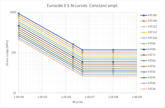
Slope m2 = 1e6 is used from knee point at Nc = 5e5 up to N = 1e8. Ncutoff = 1e8 cycles is used.
Figure 7.1: Fatigue strength curves for direct stress ranges, Variable amplitude.

Ncutoff = 1e8 cycles is used.
Figure 7.2: Fatigue strength curves for shear stress ranges.
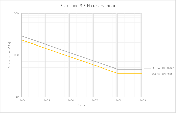
Ncutoff = 1e8 cycles is used.
Validity of the Eurocode 3 result
Please pay attention to chapter 2 “Basis of design” in Eurocode 3. The evaluation supports rivets, bolts and preloaded bolts according to category A-E according to section 3.4 and table 3.2 Eurocode 3. It is the user’s responsibility to ensure that the FE-model, chosen method, input values and results obtained by this application is suitable for his/her intended purpose, e.g. to evaluate according to a selected joint category and to apply load safety factors according to use case, e.g. operational vs. ultimate limit.
A verification model is included in the Downloads section under “Demo and verification models” where the different joints and results are tested and compared with the expected values. Solve the model and click “Bolt Report” to get the verification report.
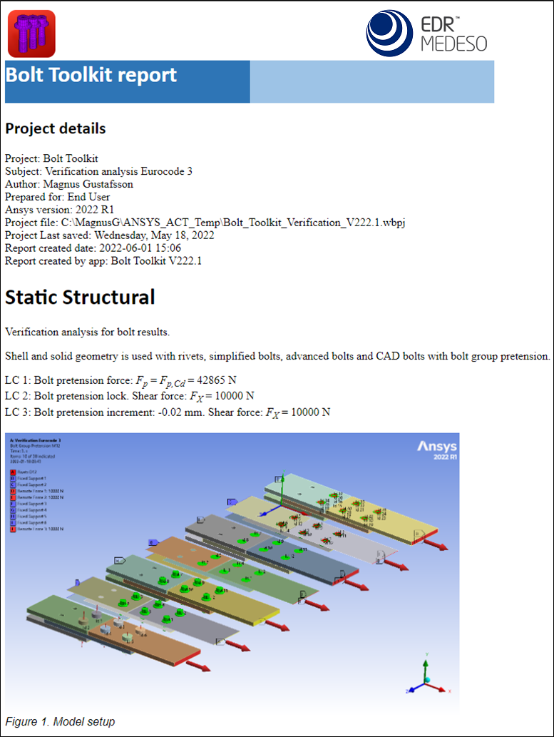
 AISC 360-16
The AISC 360-16 implementation follows the same structure as Eurocode 3 and is based on “Load and Resistance Factor Design” (LRFD) or “Allowable Strength Design” (ASD).
Reference to sections and equations from the code are shown in brackets.
The design tensile or shear strength, Rd = Φ·Rn (LRFD), and the allowable tensile or shear strength, Rd = Rn/Ω (ASD), of a snug-tightened or pretensioned high-strength bolt or threaded part shall be determined according to the limit states of tension rupture and shear rupture as:
Rn = Fn·Ab (J3-1)
Φ = 0.75 (LRFD) Ω = 2.0 (ASD)
where
Fn = nominal tensile stress, Fnt, or shear stress, Fnv, from Table (J3.2) Ab = nominal unthreaded body area of bolt or threaded part.
Material Grade
The Material Grade defined in the Material Grade table is used to select if “Allowable Strength Design” (ASD) or “Load and Resistance Factor Design” (LRFD) is used to calculate the design strength, FRd.
The adoption of AISC to the structure and naming in the app is done by the following definitions:
- Nominal tension stress; Fnt = fyb
- Ratio of nominal shear stress to tension stress; αv = Fnv/Fnt
- Partial safety factor; γM2 = Ω = 2.00 (ASD) or γM2 = 1/φ = 1/0.75 = 1.3333 (LRFD)
- Load scaling factor; γL= 1.0 (ASD) or γL= 1.5 (ASD)
- Design shear load; Fv.Ed = frv·Ab
The resulting design resistance differ between ASD and LRFD. In ASD all safety factors are applied on the material resulting in an “allowable strength” value and loads are taken with their nominal value. In LRDF material safety factors are applied on the material resulting in a “design strength” value in combination with a load factor, γL (similar to Eurocode 3). The LRDF method is designed to give the same Wuf as ASD by using γL = φ·Ω = 0.75·2.0 = 1.5.
| Material Grade | fyb [MPa] | fub [MPa] | αv | γM2 | γL |
|---|---|---|---|---|---|
| A307 (LRFD) | 388 | 310 | 0.60 | 1.3333 | 1.5 |
| A325 fully threaded (LRFD) | 775 | 620 | 0.60 | 1.3333 | 1.5 |
| A325 partially threaded (LRFD) | 775 | 620 | 0.7565 | 1.3333 | 1.5 |
| A490 fully threaded (LRFD) | 975 | 780 | 0.6013 | 1.3333 | 1.5 |
| A490 partially threaded (LRFD) | 975 | 780 | 0.7423 | 1.3333 | 1.5 |
| F3043 fully threaded (LRFD) | 1300 | 1040 | 0.5962 | 1.3333 | 1.5 |
| F3043 partially threaded (LRFD) | 1300 | 1040 | 0.749 | 1.3333 | 1.5 |
| A307 (ASD) | 388 | 310 | 0.60 | 2.00 | 1.0 |
| A325 fully threaded (ASD) | 775 | 620 | 0.60 | 2.00 | 1.0 |
| A325 partially threaded (ASD) | 775 | 620 | 0.7565 | 2.00 | 1.0 |
| A490 fully threaded (ASD) | 975 | 780 | 0.6013 | 2.00 | 1.0 |
| A490 partially threaded (ASD) | 975 | 780 | 0.7423 | 2.00 | 1.0 |
| F3043 fully threaded (ASD) | 1300 | 1040 | 0.5962 | 2.00 | 1.0 |
| F3043 partially threaded (ASD) | 1300 | 1040 | 0.749 | 2.00 | 1.0 |
When selecting a Material Grade the results “Scale Factor Value” is defined. If selecting a different Material Grade without the γL defined the “Scale Factor Value” is unchanged!
Connection Category
The evaluation of bolt joints is based on selecting a joint category that defines the criteria to use.
(a) Bolts are permitted to be installed to the snug-tight condition when used in:
- Bearing-type connections, except as stipulated in Section E6. (Category A)
- Tension or combined shear and tension applications, for Group A bolts only, where loosening or fatigue due to vibration or load fluctuations are not design considerations. (Category D or Category F)
(b) Bolts in the following connections shall be pretensioned: (Category E)
- As required by the RCSC Specification.
- Connections subjected to vibratory loads where bolt loosening is a consideration.
- End connections of built-up members composed of two shapes either interconnected by bolts, or with at least one open side interconnected by perforated cover plates or lacing with tie plates, as required in Section E6.1.
(c) The following connections shall be designed as slip critical: (Category C)
- As required by the RCSC Specification.
- The extended portion of bolted, partial-length cover plates, as required in Section F13.3.
| Connection Category | Notes |
|---|---|
| Shear connections | Bolted connections loaded in shear should be designed as one of the following. |
| A bearing | No preload required (snug-tight). Bolt class A307 or better (fy ≥ 310 MPa) may be used. |
| C slip critical | Preloaded bolt class A325 or better (fy ≥ 620 MPa) must be used. |
| Tension connections | Bolted connections loaded in tension should be designed as one of the following. |
| D non-preloaded | No preload required (snug-tight). Bolt class A307 or better (fy ≥ 310 MPa) may be used. |
| E preloaded | Preloaded bolt class A325 or better (fy ≥ 620 MPa) must be used. |
| Shear and Tension connections | Bolts subjected to both shear force and tensile force should be designed using the following. |
| F shear and tension |
Bolt hole type
| Bolt hole type (Table 3.6) | Slip factor ks | Bearing factor kb | Tearout factor kv |
|---|---|---|---|
| Normal | 1.00 | 2.4 | 1.2 |
| Oversized | 0.85 | 2.4 | 1.2 |
| Slotted (perpendicular) | 1.00 | 2.4 | 1.2 |
| Slotted (parallel) | 0.85 | 2.4 | 1.2 |
| Long Slotted (perpendicular) | 0.70 | 2.0 | 1.0 |
| Long Slotted (parallel) | 0.70 | 2.4 | 1.2 |
Class of friction surface
| Class of friction surface | None | A (one filler) | A (many fillers) | B (one filler) | B (many fillers) | Manual (one filler) | Manual (many fillers) |
|---|---|---|---|---|---|---|---|
| Plate slip factor mu | - | 0.3 | 0.3 | 0.5 | 0.5 | - | - |
| hf | 1.0 | 1.0 | 0.85 | 1.0 | 0.85 | 1.0 | 0.85 |
Hole spacing
The hole spacing is an adoption of the “clear distance”
| Spacing (Section J3.3/4/5) | Minimum |
|---|---|
| End distance (parallel) e1 (i) | 1.2·d0 |
| Inner distance (parallel) p1 | max(d + d0, 2.667·d) |
| End distance (perpendicular) e2 | 1.2·d0 |
| Inner distance (perpendicular) p2 | max(d + d0, 2.667·d) |
(i) e1
Using actual hole size, d0 instead of nominal bolt size.
Bolt Design Resistance
Design preload (minimum): Fp.Cd = Tb = 0.7·fyb·Ab (Table J3.1M)
Design tension resistance: Ft.Rd = Φ·Fnt·Ab = fyb·Ab/γM2 (J3-1)
Design shear resistance per plane: Fv.Rd = Φ·Fnv·Ab = αv·fyb·Ab/γM2 (J3-1)
Combined tension and shear resistance: F’t.Rd = Φ·F’nt·Ab = Φ·(1.3·Fnt - frv·Fnt/(Φ·Fnv))·Ab ≤ Ft.Rd (J3-2)
where: F’nt = min(Ft.Rd, Ft.Rd·(1.3 - Fv.Ed/Fv.Rd)) (J3-3a)
Design slip-resistance per plane (nominal): Fs.Rd = Φ·μ·Du·hf·Tb·ns (J3-4)
- For standard size and short-slotted holes perpendicular to the direction of the load: Φ = ks = 1.00
- For oversized and short-slotted holes parallel to the direction of the load: Φ = ks = 0.85
- For long-slotted holes: Φ = ks = 0.70
Du = 1.13, Tb = Fp.Cd, hf(one filler plate) = 1.0, hf(many fillers) = 0.85
ns = number of slip planes (= 1)
Mean slip coefficient: μ(Class A surfaces) = 0.30, μ(Class B surfaces) = 0.50
Fs.Rd = ks·μ·1.13·hf·Fp.Cd
Slip-resistance reduction factor: ksc = 1 - Tu/(Du·Tb·nb) (J3-5a)
- Tu = required (external) tension force, nb = number of bolts carrying the applied tension.
The external load per bolt is not known direct, instead the reduction factor is re-written to use the actual remaining contact force per bolt, Fc.Ed, to scale the slip resistance.
Design slip-resistance per plane (actual): F’s.Rd = ksc·Fs.Rd = (Fc.Ed/(Du·Fp.Cd))·Fs.Rd
Design bearing resistance: Fb.Rd = Φ·kb·d·tp·fu = kb·d·tp·fu/γM2 (J3-6a) (J3-6e)
- When deformation at the bolt hole at service load is a design consideration.
Hole type: “Long Slotted (perpendicular)”; kb = 2.0, All other; kb = 2.4
Design tearout shear resistance: Bv.Rd = Φ·kv·lc·tp·fu = kv·lc·tp·fu/γM2 (J3-6c) (J3-6f)
- When deformation at the bolt hole at service load is a design consideration.
Hole type: “Long Slotted (perpendicular)”; kv = 1.0, All other ; kv = 1.2
Clear distance, in the direction of the force, between the hole edges; lc = min(e1 - 0.5·d, p1-d)
Utilization Criteria
The “Utilization Factor”, Uf, is calculated for each criterion in the selected category, Uf = FEd/FRd.
The maximum utilization, Ufmax, is saved from the evaluated criteria for each bolt or rivet.
If Ufmax > 1.0 the joint does not fulfil the AISC 360-16 criteria.
The following Result Items are available depending on selected category and are printed in the output file used in the results summary in the Bolt Report.
| Result Item | Description | Category |
|---|---|---|
| Ft.Ed | Design Tension Force in bolt shaft, Ft.Ed = max(0,Fn) (Output file only) | |
| Fv.Ed | Design Shear Force, Fv.Ed = max(Fv, Fs) (Output file only) | |
| Uf_max | Max Utilization Factor from evaluated Uf in selected Category | A,-,C,D,E,F |
| Uf_shear | Ufshear = Fv.Ed/Fv.Rd | A,-,C,-,-,F |
| Uf_bearing (i) | Ufbearing = Fv.Ed/min(Fb.Rd, Bv.Rd) | A,-,C,-,-,F |
| Uf_slip (ii) | Ufslip = Fv.Ed/F’s.Rd = Fv.Ed/(Fc.Ed·Fs.Rd/(1.13·Fp.Cd)) | -,-,C,-,-,F |
| Uf_tension | Uftension = Ft.Ed/Ft.Rd | -,-,-,D,E,F |
| Uf_combined | Ufcombined = Ft.Ed/min(Ft.Rd, Ft.Rd·(1.3 - Fv.Ed/Fv.Rd)) | -,-,-,-,-,F |
(i) Uf_bearing
Ufbearing is evaluating bearing and tearout
(ii) Uf_slip
Ufslip is based on actual contact force, Fc.Ed, and if a contact is open and Fc.Ed is zero Ufslip is set to 99.
Validity of the AISC 360-16 result
It is the user’s responsibility to ensure that the FE-model, chosen method, input values and results obtained by this application is suitable for his/her intended purpose, e.g. to evaluate according to a selected joint category and to apply load safety factors according to use case, e.g. operational vs. ultimate limit.
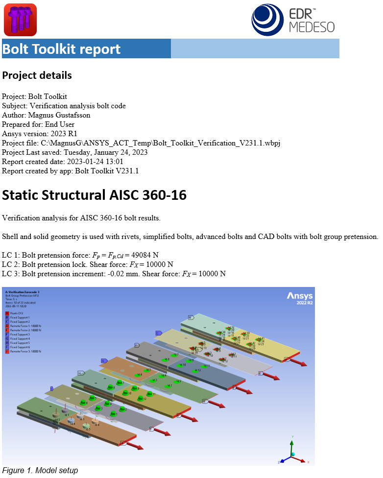
A verification model is included in the Downloads section under “Demo and verification models” where the different joints and results are tested and compared with the expected values. Solve the model and click “Bolt Report” to get the verification report.
 User Defined
The existing codes can be used as base for a user defined code by using the Bolt Settings object.