 Advanced Bolts
Table of contents
About
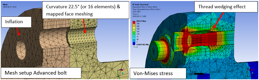
The Advanced Bolts is a load feature where so-called “Advanced Bolts” are created and placed in a group folder in the current structural (or thermal) analysis. The Advanced Bolts are constructed of linear SOLID185 or quadratic SOLID186 brick elements with frictional (or linear) contact at the head and at the thread. The thread contact section introduces the “wedge” effect when the bolt is loaded. The head contact uses “projection-based method” and contact morphing for robust contact results, see CONTA174 in Ansys help for more information. It is also possible to create a bolt/nut configuration.
The Advanced Bolts can also be added in a thermal analysis using linear SOLID278 or quadraticSOLID279 elements. The temperatures will be mapped to the structural if using the “Imported Loads”.
If doing detailed stress analysis around the bolts it is recommended to use the advanced bolts instead of the simplified bolts since the latter uses rigid (or deformable) constraints to connect to the structure and this will introduce singularities similar to a boundary condition.
The bolt dimensions are parameterized in csv files and the following bolt geometries are included: ISO-15071 “Hexagon bolt with flange”, ISO-4762 “hex socket head cap screw”, ISO-4014 “Hexagon Bolt Partly threaded shaft”, ISO-4017 “Hexagon Bolt Fully threaded shaft”. Custom bolt dimensions can easily be added by creating a new csv-file, see section “Custom Bolt Dimensions”. In addition to how the Simplified Bolts works, the Advanced bolts dimension is based on a list of valid bolts and the pretension load is calculated from the specified friction coefficient, thread pitch and pretension torque (or from the selected bolt code).
Usage
Click on “Advanced Bolts” in the toolbar inserts the Advanced Bolts Group folder in the current static analysis and creates the first Advanced Bolts load object.
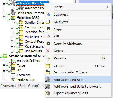
To add additional bolts right click on the Advanced Bolts Group folder and select “Add Advanced Bolts” or click on the “Advanced Bolts” in the toolbar again. You can also use “Duplicate” on an existing Advanced Bolts and modify the properties.
There is also an option Advanced Bolts to Ground used to connect a body to ground, e.g. when using compression only support.
Inputs to define the Advanced Bolts and Advanced Bolt to Ground are:
| Bolt Head | |
|---|---|
| Scoping Method | Geometry Selection/Named Selection (i) |
| Geometry | One or many edges connected to planar faces OR one or many planar faces from solid or surface body/bodies. (ii) |
| Nut/Thread | |
| Scoping Method | Geometry Selection/Named Selection |
| Geometry | One or many edges connected to planar faces from solid or surface body/bodies (Nut) OR one or many cylindrical faces from solid body/bodies (Thread). (ii) |
| Bolt Geometry | |
| Bolt Geometry File | Select bolt geometry file from the list. Default “FlangeBolt_ISO15071”. |
| Bolt Name | Select Bolt Name (dimension) from the list. |
| Shaft Diameter, ds | Read only property showing the shaft stress diameter. |
| Hole Diameter, d0 | Sets the hole search diameter if using “face selection” and is also used as the hole diameter in Bolt Strength results. |
| Head Diameter, dm | Read only property showing the head diameter. |
| Bolt Length | 0 (Default). Total length of bolt shaft including thread. Use 0 to fill the thread selection. |
| Nominal Diameter Length | 0 (Default). Length of unthreaded bolt shaft with nominal diameter. Use 0 to make the bolt shaft fully threaded using the stress area diameter. |
| Thread Start Offset | 0 (Default). Distance to offset the thread start in the selected thread hole. |
| Bolt Properties | |
| Material | Select material from “Engineering Data” or app default materials. |
| Nonlinear Effects | No (Default)/Yes. Use plasticity models defined in the selected material (iii) |
| Element Order | Linear (Default)/Quadratic. For detailed stress analysis use “Quadratic”. |
| Element Divisions | 16 (default) - 48. Number of elements around the bolt shaft. |
| Head friction | 0 ≤ 0.14 (Default) ≤ 1. Friction coefficient, μ, used in the head contact (iv) |
| Thread friction | 0 ≤ 0.14 (Default) ≤ 1. Friction coefficient, μ, used in the thread contact (iv) |
| Symmetry BC | No (Default)/Auto/Yes. Identify symmetry plane bolts. |
| Bolt Pretension | |
| Pretension from Code | Select a code to get the recommended pretension force based on Shaft Diameter and Material. Default “None”. |
| Pretension Torque | Applied bolt pretension torque used to calculate pretension force. |
| Tightening factor αA | Factor to divide the nominal bolt pretension force to account for the scatter of the achievable assembly preload from variation in friction and torque. Only used when calculating the force from pretension torque. |
| Pretension Force | Initial bolt force. If zero, the pretension section is locked. Used to define the pretension force direct and calculate the corresponding pretension torque based on friction coefficients and tightening factor. |
| Increment (Embedding) | Pretension adjustment increment. If Increment > 0 force increase. (v) |
| Load Step Apply | Load step to apply the pretension force. Used only if Pretension Force > 0. (vi) |
| Load Step Lock | Load step to lock the bolt adjustment. (vii) |
| Load Step Increment | Load step to add the Increment. Used only if Increment ≠ 0. (vii) |
| Pretension Type | Program Controlled (Default)/Pretension (PRETS179)/Joint (MPC184). Use MPC184 if there is large deformations or rotations. |
| Definition | |
| Contact Slip Radius | Radius used for normal and slip contact force summation. (viii) |
| Bolt Count | Number of bolts created. (Read only) |
(i) Scoping Method
The manual “Geometry Selection” can be converted to a “Named Selection” using the context action “Promote to Named Selection”.
(ii) Geometry
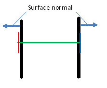
It is recommended to use solid model (including solid shell) when using the Advanced Bolts but it can be used on shell models if not using the thread option. If using a shell model make sure that the surface normal point towards the bolt head contact face (or bolt nut), see figure below, otherwise the contact will fail.
If selecting faces the “Shaft Diameter” and “Hole Diameter” defines the range for automatic hole edge search. The bolts can have different orientation and the pretension normal will be set for each individual bolt. The global Bolt face angle tolerance for the head/nut can be modified in Bolt Settings.
The head and nut/thread must only have one unique match between head and nut.
It is not allowed to have two bolt heads connecting to the same thread. This will be shown as invalid thread selection.
Virtual Topology or External Models (faceted geometry) is not supported.
(iii) Material
The following material properties (and corresponding MAPDL MP Lab) are supported: Young’s Modulus (EX), Poisson’s Ratio (NUXY), Density (DENS), Coefficient of Thermal Expansion (ALPX), Thermal Conductivity, (KXX), Specific Heat (C), Isotropic Hardening (BISO & MISO), Kinematic Hardening (BKIN, KINH). If orthotropic properties are defined the X component is automatically used (EX, NUXY, ALPX & KXX). The Bolts Pretension can be used in a thermal analysis to apply the bolt material. The pretension settings are ignored in this case.
(iv) Friction
μ = 0: No Separation, μ = 1: Bonded Always, 0 < μ < 1 Frictional contact.
The contact thread section will have no effect if bonded contact is used.
MPC formulation is used for No Separation and Bonded Always contacts.
(v) Increment (Embedding)
You may use Increment (Embedding) as “Preadjustment” if Pretension Force = 0 and Load Step Increment = 1.
(vi) Load Step Apply
The Load Steps may be defined as a “series” to define a sequential bolt pretension.
(vii) Load Step Lock
The analysis must have at least two load steps to use the Pretension Force and Lock and two or three load steps if also using the Increment. You can use the Pretension Force and only one load step if you set Load Step Apply = 1 and Load Step Lock = 2.
(viii) Contact Slip Radius
The Head Diameter is used as default radius. The solution is not invalidated if changed but a solved bolt result object must be cleared and re-evaluated to see the changes in contact normal and slip force.
A property file is also written to the solver files directory that is used by the Bolt Report feature.
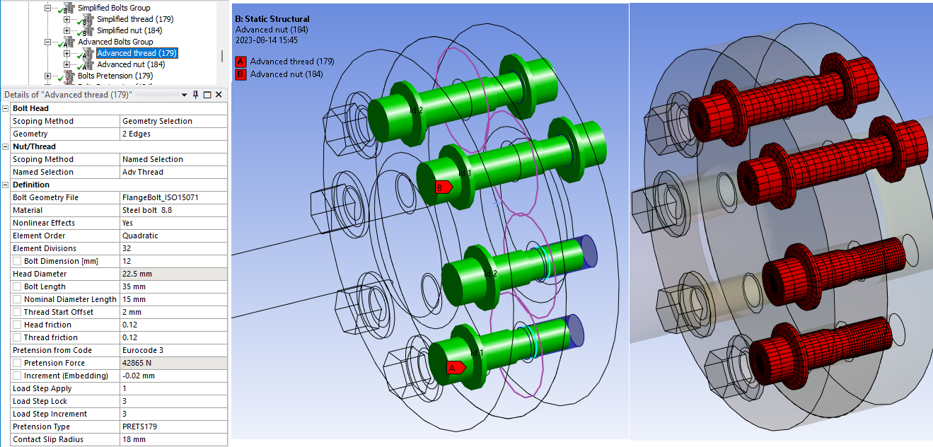
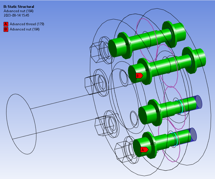
Graphics
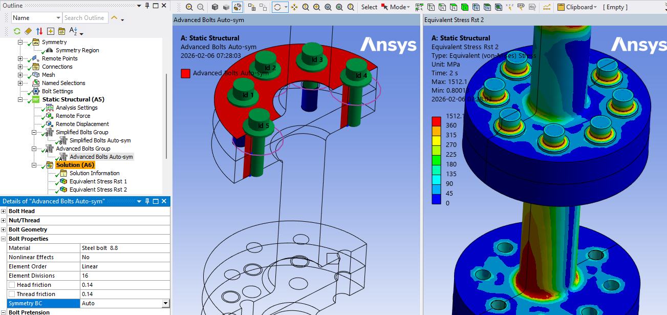
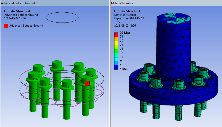
A graphic representation is created once valid inputs are given. The Advanced Bolts load object searches to connect the head and nut with the minimum distance and matching hole axis. The head geometry is plotted in red and the nut/thread in blue. The bolt geometry is plotted as a solid based on the selected bolt geometry file. If the Thread Start Offset is given a turquoise circle are plotted to indicate the thread start location. The Contact Slip Radius is plotted as a purple circle at the plane of the pretension section.
The bolt Id number is printed at the center of each bolt head. This number is used in the result tables. The colour, translucency and printing of “Id” number is defined in the Bolt Group object. The display of all bolts in the Bolts Group can be disabled by setting “Show Graphics = No”. The default values for the group can be defined in the Bolt Settings.
Meshing Recommendation
The Advanced Bolts uses frictional contacts as default, and for this to work, especially at the thread, some detailed mesh settings are needed. The bolt thread hole should have 16 elements around to match the bolt shaft and make the thread contact section work. Also use a finer mesh in the axial direction since the thread forces are active at the first few thread loops. The bolt head (or nut) contact area should have inflation with two layers using first thickness of e.g. 2 mm to make a uniform stiffness around the bolt.
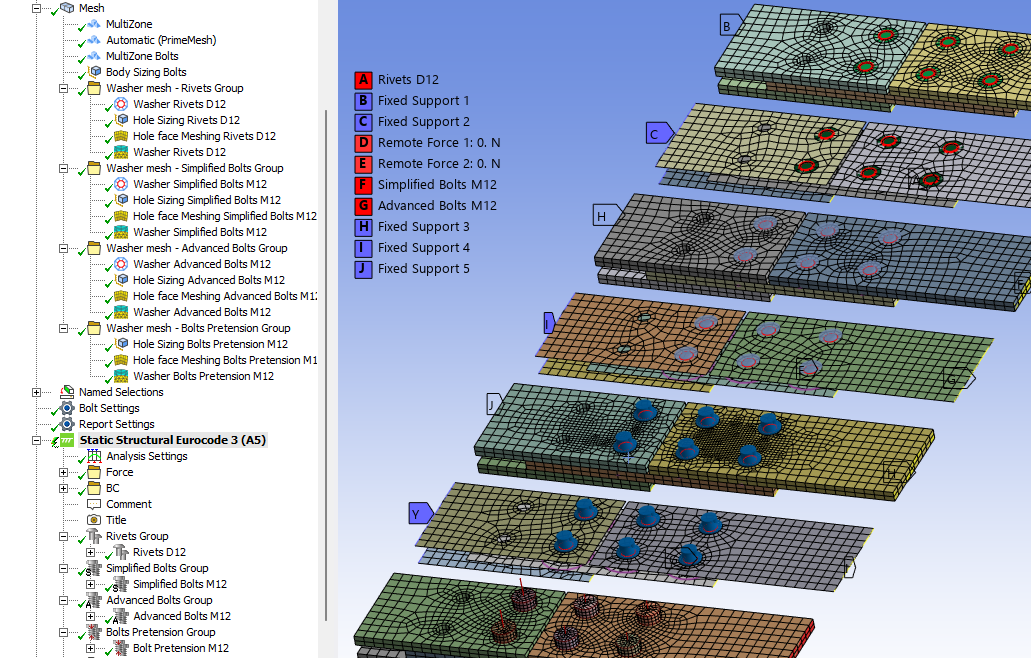
Create Washer Mesh
A “Washer” (or “Quad Layer”) mesh imprint around the bolt holes can be added using the context action “Create Washer Mesh” for an individual bolt object or on the Bolt Group.
If updating the scoping for the bolt you may use “Create Washer Mesh” again to apply the changes.
The created mesh object may be edited if needed, e.g. to change the “Number of Divisions” or “Number of Washer Layers”. For shell parts a “Quad Layer” is used and for solid parts “Sizing”, “Face Meshing” and “Inflation” objects are used.
To delete the mesh object use the context action “Delete Washer Mesh” (or delete individual objects in the model tree).
Set the Mesh>Automatic Method “Sheet Body Method = PrimeMesh” or assign the mesh “Method = Automatic (PrimeMesh)” to the shell parts.
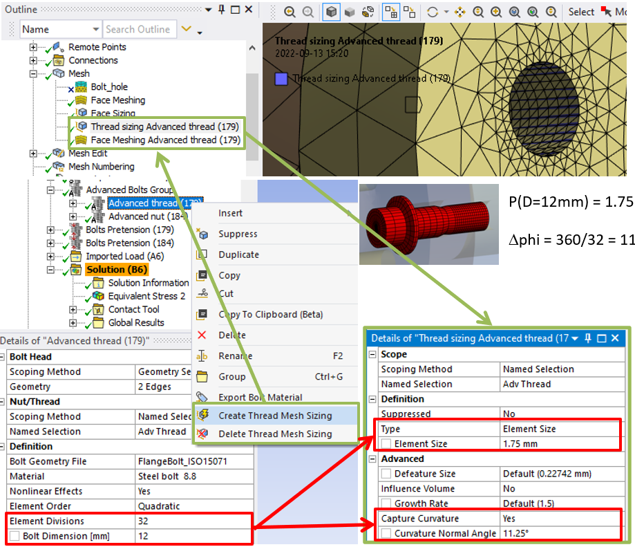
Thread mesh sizing
The number of element divisions can be defined for advanced bolts in the range from 16 to 48. A thread mesh sizing can be defined that is linked to the element divisions and thread pitch size, P, by right-clicking on the bolt objects and selecting “Create Thread Mesh Sizing”.
The created mesh sizing may be deleted using the option “Delete Thread Mesh Sizing”.
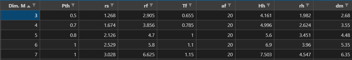
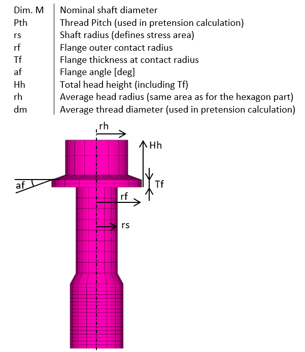
Bolt Geometry
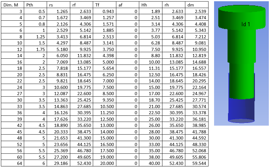
The bolt geometry is based on tabulated values (in mm) from a csv file found in the extension installation folder. The files are updated to include the “Name” for each bolt size and this name is used when selecting the bolt.
A partly threaded bolt is defined using the parameter “Nominal Diameter Length”.
The thread mesh outer diameter is defined from the selected cylindrical face for best contact match.
Custom Bolt Geometry
The user can create custom bolt tables using the Advanced Bolt Editor in the Bolt Settings.
The Advanced Bolt Editor makes it easy to view or edit a bolt table in other units, e.g. “inch” or “m”.
The bolt tables can also be created following these steps:
- Open the default file (FlangeBolt_ISO15071.csv) in e.g. Excel.
- Edit the values according to your specifications. Unit must be in mm and degrees. Note that the relation rf > abs(rh) > rs must be valid otherwise the mesh will be corrupt. If rf = rh the flange is removed. If rh < 0 a hex socket bolt head is made. The socket min depth, t, and socket radius, rsock, are based on the head radius, rh, according to: t = 0.0051rh2-0.5943rh, rsock = -0.5281rh. (Based on ISO4762 geometry)
- Save the table as a csv-file in the extension installation folder for the current Ansys version. (%AppData%\Ansys\v2XY\ACT\extensions\BoltToolkit_V2XY.Z)
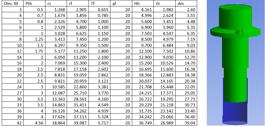
Bolt Geometry Files
The sample image of each bolt shows a partly threaded bolt using the parameter Nominal Diameter Length.
FlangeBolt_ISO15071.csv
HexSocketHead_ISO4762.csv (Fully threaded shaft)
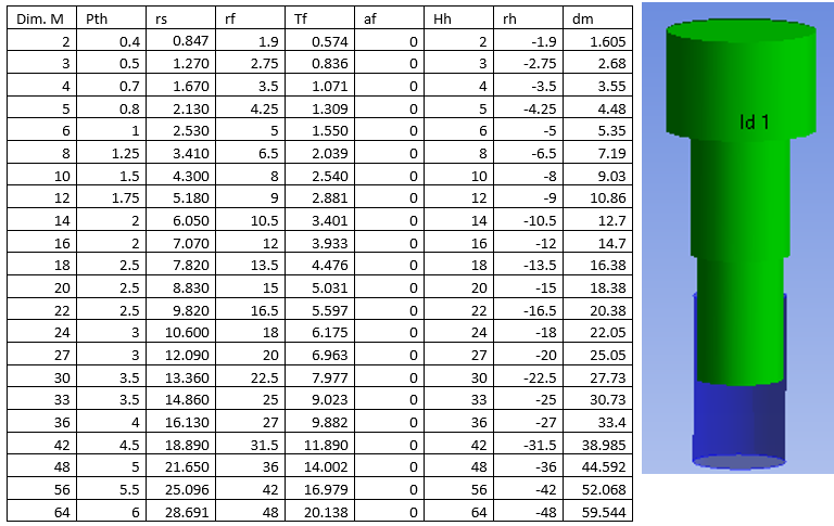
The Nominal Diameter Length must be zero for the bolt to be “fully threaded”.
The socket hole is not visible in the graphics.
HexagonHead_ISO4014.csv (Partly threaded shaft)
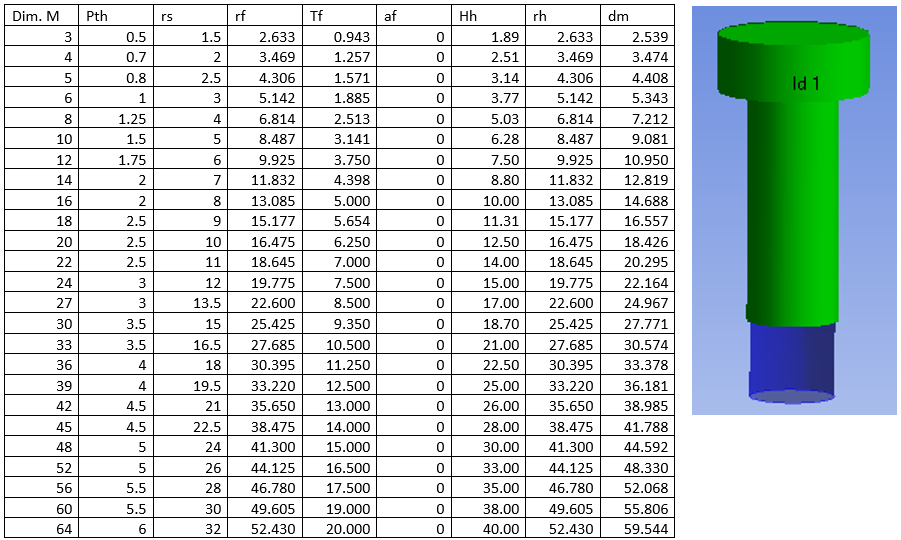
The stress radius (rs) is equal to the nominal shaft radius.
The Nominal Diameter Length does not impact the bolt shaft diameter.
HexagonHead_ISO4017.csv (Fully threaded shaft)
The Nominal Diameter Length must be zero for the bolt to be “fully threaded”.
This bolt can be used instead of ISO4014 by setting the Nominal Diameter Length > 0.
Symmetry BC
Using “Symmetry BC = Auto” will identify all bolts with a single half circle edge at the bolt head as symmetry bolts. Using “Symmetry BC = Yes” will identify all bolts in the group that has a half circle or slotted hole as symmetry bolts. The graphics will mark symmetry bolts with a red plane along the bolt shaft. A symmetry bolt is meshed in half and the cut plane nodes are constrained in the normal direction. The pretension force is automatically reduced to 50% for the symmetry bolts.
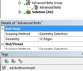
Contact adjustment
By default the CNCHECK,MORPH option is used in order to align the bolt head and thread contact nodes with the target elements for improved contact convergence. If you for some reason do not want to use this, you may tag the bolt object with the tag “advboltnomorph” to exclude that bolt object from morphing. The default behavior for “advboltnomorph” can be defined using the property “Advanced Bolts Contact Morph” in the Bolt Settings.
Pretension Calculation
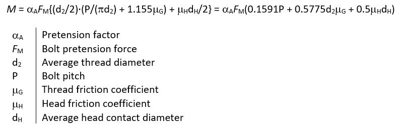
The bolt pretension force is calculated based on the bolt geometry details given in the bolt geometry file (Pitch and average thread diameter), the bolt hole diameter and the bolt torque and friction details. The relation between the pretension torque, M, and pretension force FM is defined by the following equation (based on VDI 2230 equation: (R13/1)).
Tightening factor
The Tightening factor is defined as the range of pretension force:
αA = FM maxFM min ≥ 1 and Fpretension = FM max/αA.
The scatter amplitude is defined as:
(FM max – FM min)/(FM max + FM min) = (αA – 1)/(αA + 1)
The definition follows VDI 2230 section 5.4.3 [4]. Guide values for the tightening factor are found in VDI 2230 table A8 [4].
The tightening factor can also be used to account for embedding in the joint that will reduce the pretension force. See the section Embedding calculation for more details.
Embedding calculation
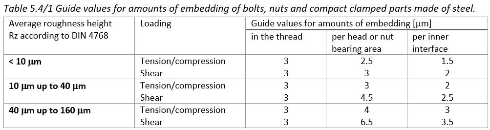
The bolt pretension is usually reduced due to relaxation of the bolt and local plastic deformation in the bolt head and thread contacts as well as the joint contacts. If the analysis is based on linear elastic material properties, these relaxation effects can be included by reducing the nominal bolt adjustment (elongation) with the embedding from the different contact zones. Common values for embedding are found in VDI 2230 table 5.4/1, see below. The total sum of embedding for a bolt joint is; δembedd.
To calculate the reduced bolt pretension due to embedding a nominal pretension analysis is made first where the total bolt joint adjustment, δAdj, is extracted. Use the Bolts Result to list the Adjustment.
The tightening factor is defined as: αA = δAdj/(δAdj – δembedd)
Advanced Bolts to Ground
The Advanced Bolts to Ground_ works in the same way as the “Beam Body-Ground”. Based on the Bolt Head scoping and Bolt Length bolts are created and pretension force can be applied just as for the standard Advanced Bolts. In a structural analysis the end of the bolt is locked in all degrees of freedom.
In both structural and thermal analyses, the environment (or initial) temperature is applied to the fixed end of the bolt and the temperature will be interpolated/mapped along the bolt shaft.
