 Bolts Pretension
Table of contents
About
The Bolts Pretension is a load object that can be used to simultaneously apply the same material and bolt pretension to multiple solid or line body bolts.
The Bolts Pretension is placed in a group folder in the current structural (or thermal) analysis. The recommended pretension load can be automatically calculated based on the selected bolt code, material and shaft diameter. The identified shaft diameter can be changed to influence the pretension force calculation.
Post processing of the Bolts Pretension is done using the Bolts Strength of Bolts Fatigue object.
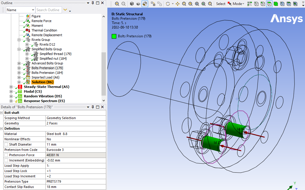
Usage
Click on “Bolts Pretension” in the toolbar to insert the Bolts Pretension Group folder in the current static analysis as well as creating the first Bolts Pretension load object.
To add additional pretensions, right click on the Bolts Pretension Group folder and select “Add Bolts Pretension” or click on “Bolts Pretension” in the toolbar again. You can also use “Duplicate” on an existing Bolts Pretension and modify the properties.
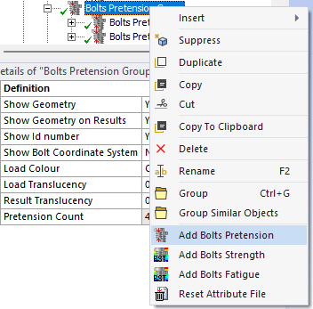
Inputs to define the Bolts Pretension are:
| Bolt Shaft | |
|---|---|
| Scoping Method | Geometry Selection/Named Selection (i) |
| Geometry | One or many cylindrical solid body faces (ii) OR straight line body edges. |
| Definition | |
| Material | Select material from “Engineering Data” or app default materials (iii). |
| Nonlinear Effects | No (Default)/Yes. Use plasticity models defined in the selected material (iii) |
| Shaft Diameter, ds | Bolt shaft diameter identified from selected geometry. |
| Hole Diameter, d0 | Used as the hole diameter in Bolt Strength results. |
| Pretension from Code | Select a code to get the recommended pretension force based on Shaft Diameter and Material. Default “None”. |
| Pretension Force | Initial bolt force. If zero, the pretension section is locked. |
| Increment (Embedding) | Pretension adjustment increment. If Increment > 0 force increase. (iv) |
| Load Step Apply | Load step to apply the pretension force. Used only if Pretension Force > 0. (v) |
| Load Step Lock | Load step to lock the bolt adjustment. (vi) |
| Load Step Increment | Load step to add the Increment (Embedding). Used only if Increment ≠ 0. (vi) |
| Pretension Type | Program Controlled (Default)/Pretension (PRETS179)/Joint (MPC184). Use MPC184 if there is large deformations or rotations. |
| Contact Slip Radius | Radius used for normal and slip contact force summation. (vii) |
| Pretension Count | Number of pretensions created. (Read only) |
(i) Scoping Method
The manual “Geometry Selection” can be converted to a “Named Selection” using the context action “Promote to Named Selection”.
(ii) Geometry
Selection of two half cylinders on one shaft is possible. The bolts can have different orientation and the pretension normal will be set for each individual bolt. Virtual Topology or External Models (faceted geometry) is not supported.
(iii) Material
The following material properties (and corresponding MAPDL MP Lab) are supported: Young’s Modulus (EX), Poisson’s Ratio (NUXY), Density (DENS), Coefficient of Thermal Expansion (ALPX), Thermal Conductivity, (KXX), Specific Heat (C), Isotropic Hardening (BISO & MISO), Kinematic Hardening (BKIN, KINH). If orthotropic properties are defined the X component is automatically used (EX, NUXY, ALPX & KXX).
The Bolts Pretension can be used in a thermal analysis to apply the bolt material. The pretension settings are ignored in this case.
Selecting a Material will override any Material Assignment for the bolt bodies and create a new independent material.
(iv) Increment (Embedding)
You may use Increment (Embedding) as “Preadjustment” if Pretension Force = 0 and Load Step Increment = 1.
(v) Load Step Apply
The Load Steps may be defined as a “series” to define a sequential bolt pretension.
(vi) Load Step Lock
The analysis must have at least two load steps to use the Pretension Force and Lock and two or three load steps if also using the Increment. You can use the Pretension Force and only one load step if you set Load Step Apply = 1 and Load Step Lock = 2.
(vii) Contact Slip Radius
The double Shaft Diameter is used as default radius. The solution is not invalidated if changed but a solved bolt result object must be cleared and re-evaluated to see the changes in contact normal and slip force.
A property file is also written to the solver files directory that is used by the Bolt Report feature.
Graphics
The bolt body related to the selected bolt shaft face is shown in transparent green colour. The identified pretension normal is drawn as a red arrows at each bolt shaft together with an Id number used in result tables. The Contact Slip Radius is plotted as a purple circle at the plane for the pretension section.
Meshing Recommendation
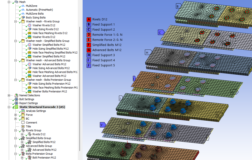
The bolt body can be meshed using the “Multizone” method and a body “Sizing”.
A “Washer” (or “Quad Layer”) mesh imprint around the bolt holes and “Thread sizing” can be added by first creating corresponding “dummy” Advanced Bolts and then using the context action “Create Washer Mesh” and “Create Thread Mesh Sizing” on the bolt object. Then suppress (or delete) the Advanced Bolts object to avoid double bolts in the bolt holes!
Migration of “Bolts Pretension” to “Bolts Pretension Group”
In previous versions of Bolt Toolkit the Bolts Pretension objects was not grouped in the same way as the Simplified/Advanced Bolts. Opening an old project will continue to work and solve, however the existing pretension objects can easily be migrated to the Bolts Pretension Group.
- Select the Bolts Pretension objects in the model tree and click Save Bolt Configuration.
- Select the “Analysis” and click Import Bolt Configuration and select the “BoltToolkit.json” file.
- After verifying the new objects delete the old “Bolts Pretension” objects in the model tree (outside of the Bolts Pretension Group).
- Update the “Bolt Object” in any strength or fatigue result objects and select the new object.
 Sequential Bolt Pretension
All bolt features now support definition of sequential pretension within one bolt object.
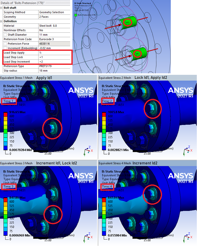
To set up sequential pretension define the geometry scoping of the bolt shaft (Bolts Pretension) or bolt head (Simplified Bolts and Advanced Bolts) in the order you want them to be pretensioned. The order is the same as the Id number shown in the graphics window.
The printing of Id number can be turned off in the Bolt Settings (or the preference file “showBoltId = False”).
The “Load Step Apply/Lock/Embedding” supports the following syntax for defining the order.
- Single integer “1”: All selected bolts are loaded at this step (default).
- List of integers “1,2,3,4” or “1,2,1,2”: Each bolt is loaded at the corresponding step in the list.
- Incomplete list of integers “1,2”: If more bolts are selected than items in the list the step increment of the last two items is used for the remaining bolts.
- Series of integers with increment one “1:4”: Each bolt is loaded at the corresponding step based on step increment of one, i.e. “1,2,3,4”.
- Incomplete series of integers “1:”: Each bolt is loaded starting at first given step and then with step increment of one, i.e. “1,2,3,4…”.
- Series of integers with custom step “1:2:7”: Each bolt is loaded at the corresponding step based on the given step increment, i.e. “1,3,5,7”.
- Increment to Load Step Apply “+1”: The Lock or Embedding is activated based on the Apply step plus the given step increment.
 App default material
Bolt Toolkit contains a list of default materials for use with rivets and bolts. The material properties are saved in a “dictionary” in the app installation folder in the file “Materials.json” (same location as the preference file). This file can be edited using e.g. Visual Studio Code or other text editors with plugins for “json” format.
The selected rivet/bolt material (from Engineering Data) can be exported and included in the app default materials.
Right-click on a rivet/bolt and select “Export Rivet/Bolt Material” to export the selected rivet/bolt material (from Engineering Data) to be included in the app default materials and be available for future analyses.
Keep a backup copy of the file. When installing a new version of Bolt Toolkit you may replace the default file with your custom version.
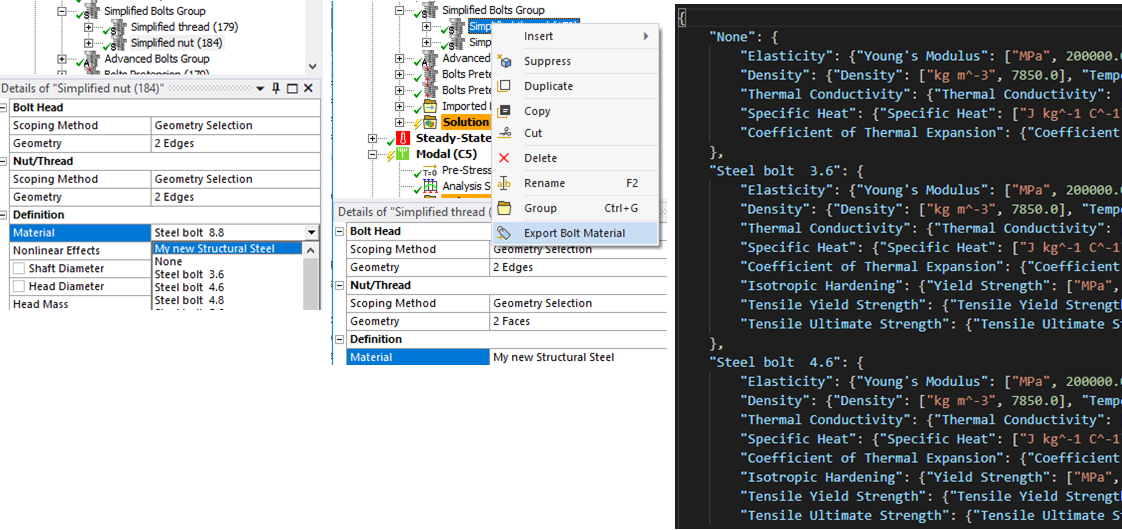
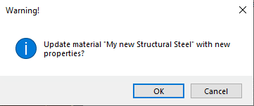
If the Engineering Data material name already exists in the bolt material list you get the option to update the material with the new properties defined in Engineering Data. If exporting a default material, e.g. “Steel bolt 8.8” nothing happens.
The properties “Tensile Yield Strength” (Ry) and “Ultimate Yield Strength” (Rm) if defined are used in Rivets/Bolts Result when post processing Eurocode 3. These properties are not to be confused with the yield limit used in isotropic and kinematic hardening plasticity material models.
The structural material properties for the default materials are listed in the following table.
The material “None” is used to not modify the existing material of the bolt part assigned by Mechanical.
All bolt materials uses the same linear properties.
- Young’s modulus: 200 GPa
- Poisson’s ratio: 0.3
- Density: 7850 kg/m3
- Coefficient of Thermal Expansion: 1.2e-05 -/C
- Thermal Conductivity: 60.5 W/(m*C)
- Specific Heat: 434 J/(kg*C)
The “Bilinear Isotropic Hardening” (BISO) uses the “Tensile Yield Strength” (Ry) as the yield limit and a tangent modulus of 1000 MPa.
| Material Name | Ry [MPa] | Rm [MPa] |
|---|---|---|
| None | ||
| Steel bolt 3.6 | 180 | 300 |
| Steel bolt 4.6 | 240 | 400 |
| Steel bolt 4.8 | 320 | 400 |
| Steel bolt 5.6 | 300 | 500 |
| Steel bolt 5.8 | 400 | 500 |
| Steel bolt 6.8 | 480 | 600 |
| Steel bolt 8.8 | 640 | 800 |
| Steel bolt 9.8 | 720 | 900 |
| Steel bolt 10.9 | 900 | 1000 |
| Steel bolt 12.9 | 1000 | 1200 |
| Steel bolt 14.9 | 1260 | 1400 |
| Steel bolt A307 | 310 | 388 |
| Steel bolt A325 | 620 | 775 |
| Steel bolt A490 | 780 | 975 |
| Steel bolt F3043 | 1040 | 1300 |