
 Weld Strength
Table of contents
About
The “Fillet Weld Strength” and “Butt Weld Strength” is used to post process welds according to Eurocode 3, AISC 360-16 or other codes. The new code EN 1993-1-14:2025 Eurocode 3 chapter “8.1 Ultimate limit state” outlines a number of analysis methods depending on stability and buckling.
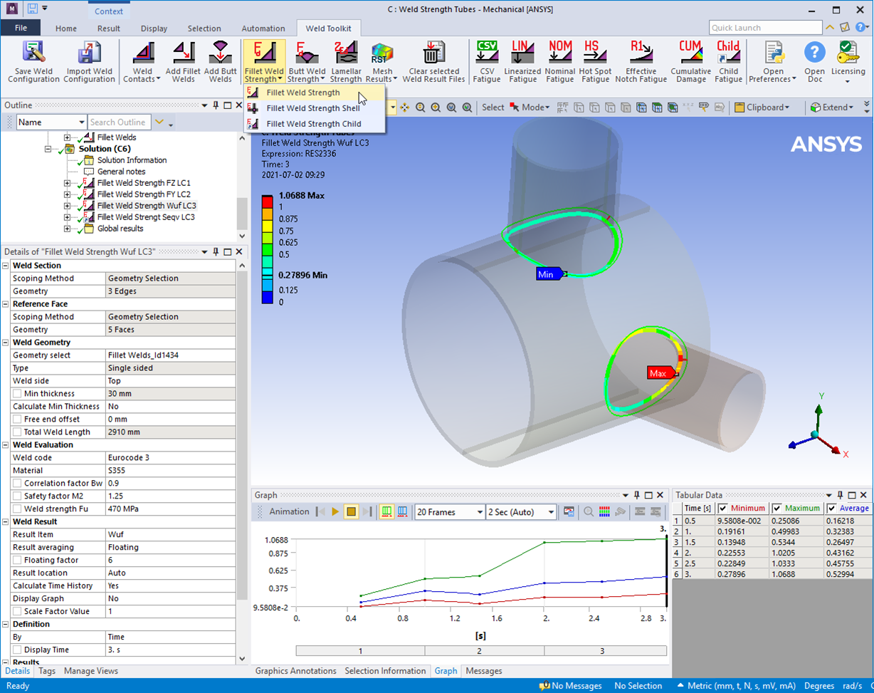
This result object will extract all relevant information from the selected weld object and create a results summary listing.
Usage
Weld strength result objects can be added in two ways:
-
Click the “Fillet/Butt Weld Strength” button to add the corresponding result object to the current solution (Static, Transient, Random Vibration, Response Spectrum).
-
Use the context action “Add Fillet/Butt Weld Strength” on the Weld Group or the Weld object OR the “Add Parent results” on the Weld Child Setup.
Multiple weld sections can be selected in one result object and the sections are automatically grouped into different groups based on the edge connectivity.
Inputs to define the Weld Strength are defined in the table below.
| Weld Section | |
|---|---|
| Scoping Method | Geometry Selection (Default)/Named Selection |
| Geometry | Weld section edges at the weld root. |
| Reference Face | |
| Scoping Method | Geometry Selection (Default)/Named Selection |
| Geometry | Reference Faces connected to the Weld Section edges. |
| Weld Geometry | |
| Geometry select | Manual select (Default)/Manual select weld part/Weld object (ii) |
| Type (Fillet weld) | Single sided (Default)/Double sided/Single sided intermittent/Double sided intermittent. See Type below. |
| Type (Butt weld) | Butt weld (Default)/Butt weld intermittent/Butt weld Double sided/Butt weld Double sided intermittent. See Type below. |
| Weld side | Top/Bottom/Top&Bottom/Reference Face. Position of the weld seam in relation to the Reference Face See Weld side below. |
| Throat thickness | Throat thickness amin (Default 3 mm) (Previously named “Min thickness”) |
| Calculate Throat thickness | No (Default)/Yes Flag to indicate if weld thickness will be calculated. |
| Free end offset | Inactive weld length on an open weld chain (Default 0 mm). Used to calculate total effective weld length. |
| Weld fraction | Ratio of Total Weld Length to Total Section Length, Lweld/Lsection (Visible for intermittent welds). |
| Total Weld Length | Length of the weld seam Lweld to help estimate welding time and cost (Read only). |
| Weld Evaluation | |
| Weld Code | Weld Code to use. |
| Material | Select material class. (Sets Fy, Fu, αw, βw, γM2 and γL) (Default “S235”) |
| Factor, alfaw | Correlation factor αw > 0 (Default 0.6) |
| Factor, betaw | Correlation factor βw > 0 (Default 0.8) |
| Safety factor, gammaM2 | Partial safety factor γM2 > 0 (Default 1.25) |
| Yield strength, Fy | Nominal yield tensile strength fy >= 0 (Default 0 MPa) |
| Ultimate strength, Fu | Nominal ultimate tensile strength fu > 0 (Default 360 MPa) |
| Filler strength, FuFM | Nominal ultimate tensile strength filler material fu.FM > 0 (Default 0 MPa) (iii) |
| Weld Result | |
| Result Item | Select a Result Item to display. |
| Result averaging | Floating (Default)/Segment/Section (linear)/Section (constant)/Group. See Result averaging |
| Floating Factor | Default value from selected Weld Code. Type “0” to reset to Default value. (Visible for Floating) |
| Segment Length | Default L = Floating Factor·amin. L is adjusted to fit Total Weld Length. (Visible for Segment) |
| Result Location | Weld stress Result Location of weld stress. |
| Stress Type | Absolute Stress (Default)/Positive Stress. Impacts the Wuf calculation. |
| Calculate Time History | No (Default)/Yes/Yes (Maximum Over Time)/Yes (Minimum Over Time). |
| Display Graph | No (Default)/Yes. If “Calc Time History=No” the path result is displayed in the Graph window. |
| Scale Factor Value | Scale factor on the calculated loads, e.g. load factor γL (iv). |
| Definition | |
| By | Time (Default)/Result Set/Maximum Over Time/Time Of Maximum (standard Mechanical feature) (iv). |
| Display Time | Load step time for results evaluation (v). |
Note that Output Controls “Nodal Forces = Yes” and Analysis Data Management “Save MAPDL db = Yes” in Analysis Settings in order for post processing to work. When adding the first weld object these setting are automatically set to “Yes”.
(ii) Geometry select
To post-process an Add Fillet Weld or Virtual Weld select the object from this list. To avoid duplicate names the weld object Id number is appended to the name. When selecting a weld object the weld scoping and dimensions are retrieved.
Starting in 2024 R2 the Weld Offset is always included in the evaluation for single and double-sided welds.
(iii) Filler Strength, FuFM If FuFM = 0, then FuFM = Fu, i.e. equal strength of base and filler material.
Eurocode 3 is updated to combine Fu and FuFM in the expressions for design resistance.
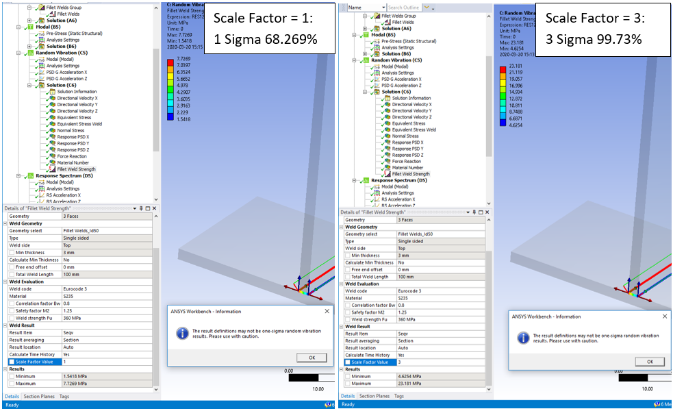
(iv) Scale factor value
In a Random Vibration analysis this sets the probability of the results (1: 68.269%, 2: 95.45%, 3: 99.73%).
(iv) By
You may use Maximum Over Time to get the worst case from all steps. In addition, the Graph displays the time history of min and max for the selected result.
In V2025.20 the Maximum Over Time changes to use the much faster option “Calculate Time History = Yes (Maximum Over Time)”.
(v) Display Time
You may only use time steps where there are results saved, see the graph and tabular data window for load steps to use.
Weld Section
Select edges of a shell or solid model along the weld seam line.
This is the location where the results are plotted.
The order the edges are selected are used to define the path direction. The edge can be a shared edge in a shell or a multi-body part or a free edge from a contact face of a weld.
Edge to surface contacts as well as mesh connections are allowed. See Table 3 of pictures for valid selections.
The section “Reference Id” number is plotted in graphics for the weld result. The visibility can be changed using the Weld Group property “Show Id number” or in the Weld Settings.
Reference Face
For each weld section edge select a corresponding connected face. The face is used to define the local nodal coordinate system used to project the section forces and moments on, see Table 3 of pictures for valid selections.
The reference face should be selected from the part that is welded, meaning that the section forces are extracted from the part the reference face belongs to.
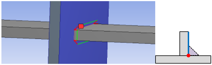
Shared face for solid models
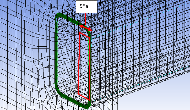
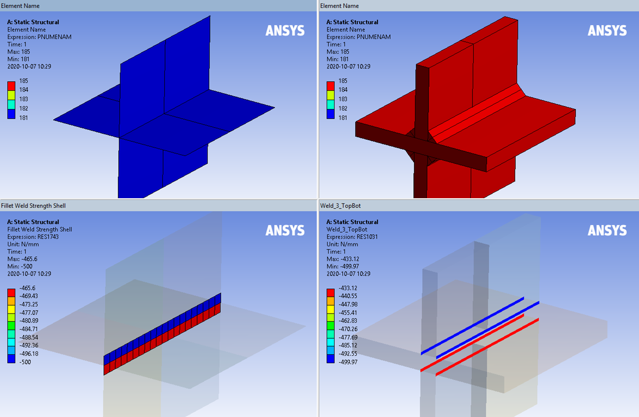
If using surface to surface contact or multi-body parts to connect the model without weld elements the app will find the contact/shared face, marked green in the figure below, to extract the forces. This may be one and the same face for all edges of the weld section.
The app will re-select nodes from the face using the weld section length and 5 times the weld Throat thickness, a, in depth to get the local forces for the weld section and not include nodes from the other side. The force listing is done once using the initial defined value of Throat thickness. Type in “0” to reset to the default value (3 mm).
Updating the Throat thickness re-use the existing forces. To force a re-evaluation of the nodal forces select the weld object and click Clear selected Weld Result Files before evaluate the result again. To avoid selecting too few or too many nodes (depending on geometry) you may:
- Set the initial Throat thickness, a, so that the 5·a selects the desired depth for extracting the weld forces.
- Split the shared face (in Design Modeler or SpaceClaim) so each weld section edge has each unique contact/shared face.
Bonded contact vs. multi-body
Using bonded contact for the weld is preferably for two reasons.
- It is easier to mesh and you can easily use parameters on geometry.
- The weld forces are evaluated based on the contact forces or the underlying elements.
In a multi-body part the root edge of the weld part is shared in two shared faces that will cause an error in the reaction force summation. In the contact section the forces are derived from the contact side of the contact pair.
To have the best results you must make sure that the contact side is on the weld part and to use Behavior = “Asymmetric” and Formulation = “Augmented Lagrange”, since the contact side normally has the finer mesh. The Create Weld contacts will use these settings.
With the new Weld Strength Settings option Weld Force Extraction = “Underlying Element” bonded contacts with Formulation = “MPC” are allowed even though they don’t save contact results. For solid models without weld parts this does not influence the result quality.
Note that “Program Controlled” formulation may use “MPC” so make sure that e.g. “Augmented Lagrange” or “Pure Penalty” formulation is used if setting the option Weld Force Extraction = “Contact Element”.
Edge to surface contact for both shell parts and solid parts are also allowed and has the same result quality as multi-body parts, i.e. the results will be based on nodal forces.
Weld Geometry
Geometry select
Use “Manual select” to post process welds defined by multi-body, node merge or contacts with no physical weld part.
Use “Manual select weld part” to post process fillet welds defined by a geometry part.
Welds defined with the “Add Welds” (Fillet/Butt/Virtual Welds) must be selected from this list otherwise the weld results are not identified. Selecting an existing weld in the list will select Weld Section, Reference Face, Type, Throat Thickness, Free end offset and Weld fraction automatically. You may edit and reorder or reduce the number of Weld Section edges.
Weld Offset
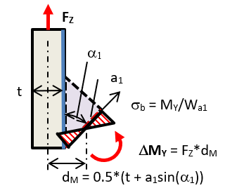
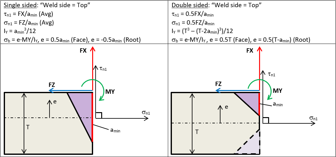
In a single-sided weld without weld elements (shell or solid) a vertical force will create a bending moment, ΔMY, based on the shell or solid part thickness and the weld throat size. The moment is added to the existing bending moment, MY, and will impact the bending stress calculation.
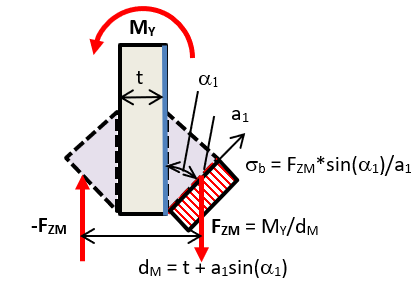
In a double-sided weld without weld elements (shell or solid) a bending moment, MY, is balanced by an internal force pair, FZM, in the throat section. This force is used to calculate the bending stress, σb, (normal to the section). This force contributes to the normal and shear stress evaluation to handle bending effects correct. The force does not contribute to the reaction force, FZ (axial), since it is an internal force pair.
For a solid weld or “Add fillet weld” the offset effect is included automatically from the reaction forces and moments in the elements of the weld section.
Also look at the section Result Location down on this page.
Type
Type of fillet weld, see “Table 3” figure below.
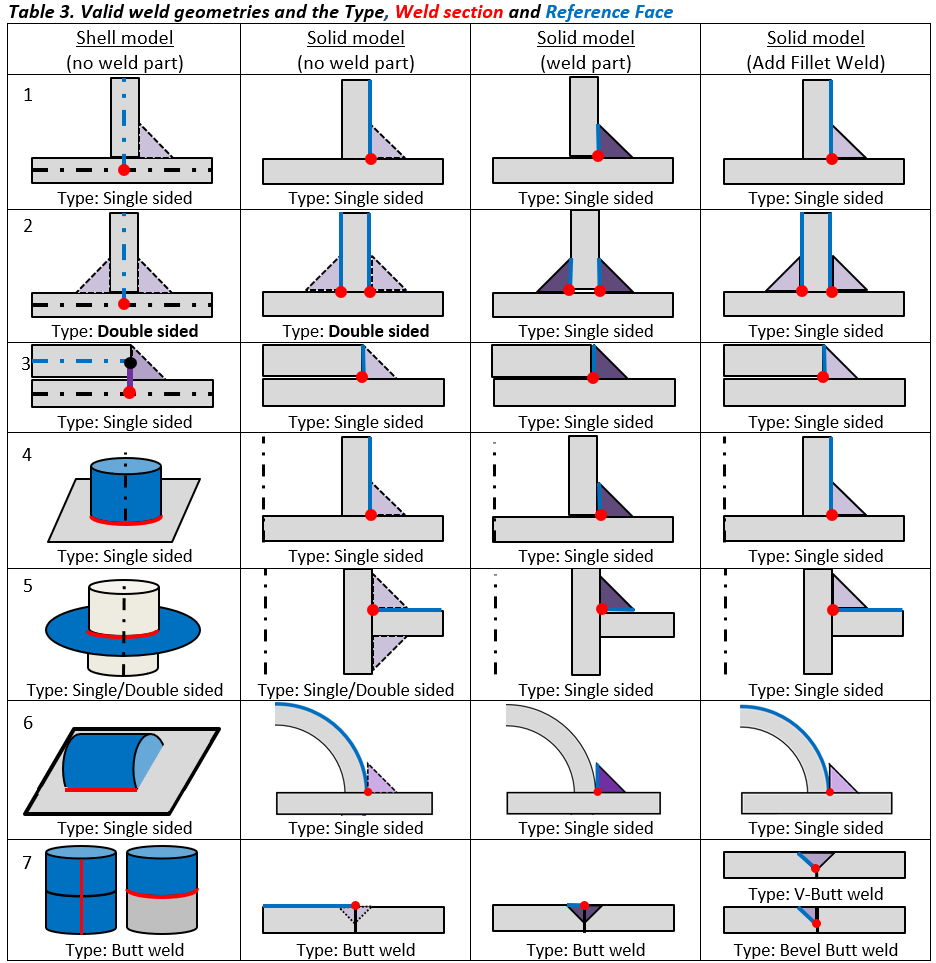
Weld section
One special case is the double-sided solid model without weld elements (row 2 & 5, 2nd column in Table 3). You must use Type: “Double Sided” since the weld forces are evaluated from one common contact or shared face. In 2024 R2 the weld wire frame graphics is updated to display the “bottom” side weld at correct place accounting for the shell or solid part thickness.
Type
The “Type” relates to the number of welds that are connected to the “Weld section” selection and not direct to the weld joint type whether it is a physical single or double-sided weld joint. This simply sets the scale factor on the forces to correctly evaluate the weld stress.
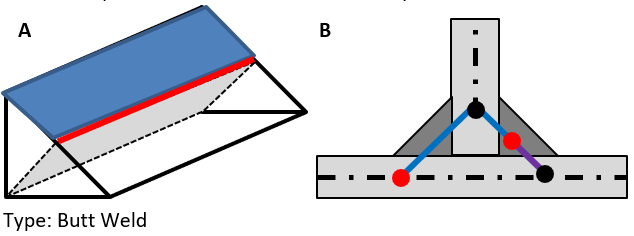
Weld parts
In previous versions of the Weld Strength app an alternative method for evaluation a filled weld was described. This method is not needed anymore since the weld section is placed correct using the “Weld Side” property but there are still two cases where this method is needed. In a model with weld elements where the weld part is divided at the throat section (A) the “Butt weld” must be used to position the weld section correctly. The same is also valid for a shell model (B).
Cruciform joints
In a cruciform joint make sure to select correct section and edge. In the case below where one continuous horizontal part connects to one vertical through a cut out.
Flare-Bevel Groove Weld
In a T-joint between rounded profiles of the same size modelling and analyzing the weld strength is tricky. A fillet weld in the inner corner “transforms” to a butt weld on the flush faces. First option is to extend and merge the solid part and then split and use “Shared Topology”. Second option is to create a mid-surface model also using “Shared Topology”. You find this demo model including results setup from this link: Flare-Bevel-Groove-Weld.wbpz (Ansys 2023R1).

Weld side
The weld throat section location is displayed as a red (throat thickness) and green lines. The location can be flipped using the property “Weld Side”.
- For a model without weld elements the user may select one specific Weld side for a single sided weld (Top or Bottom).
- A double-sided weld can also be evaluated for each side individually or the worst from both sides at the same time by using the combined “Top/Bottom” option.
- For a solid model with weld contacts the Weld Side property will also control where to find the contact elements to extract the weld forces.
- For a butt weld the Weld side defines the placement of the Result Location “Throat (Face)”.
- For a Virtual butt weld the option “Weld side = Reference Face” is used to select the Reference Face as the location where the forces are extracted. This is useful if the section is not perpendicular to the top face or to evaluate a “laser weld” imprint connecting two planar parts via a bonded contact.
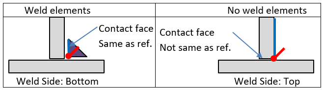
For a multi-body part the app will always look for a shared face connected to the weld section edge. It will start by checking if the reference face is the shared face as in the left figure above and then check for the other face.
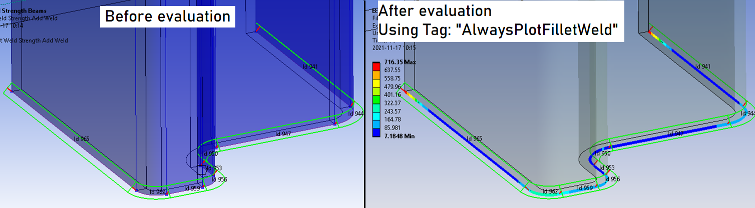
Weld Graphics
The weld geometry wire frame graphics is shown before evaluating the result. The graphics accounts for shell and solid body thickens as well as indicating the selected Result Location.
To always show the weld graphics on results set the Weld Group property “Show Geometry on Results = Yes”. The weld section id number can be show/hidden by using the corresponding property “Show Id number = Yes/No”.
In case of invalid scoping only the Id numbers causing the error are plotted.
The default values for the weld group can be defined in Weld Settings.
Weld Evaluation
The options for weld code evaluation are described in the Design Codes section.
Weld Result
The selected “Result Item” is displayed on the Weld Section edges.
Result Items
| Result Item | Description |
|---|---|
| Node Id | Weld Section Node number (output file only) |
| Group Id | Weld Section Group number (output file only) |
| Sect Id | Weld Section edge “Referenced Id” (output file only) |
| Path pos | Section path position or Weld section edge length (Node Id = 0) or group length (Sect Id = 0) |
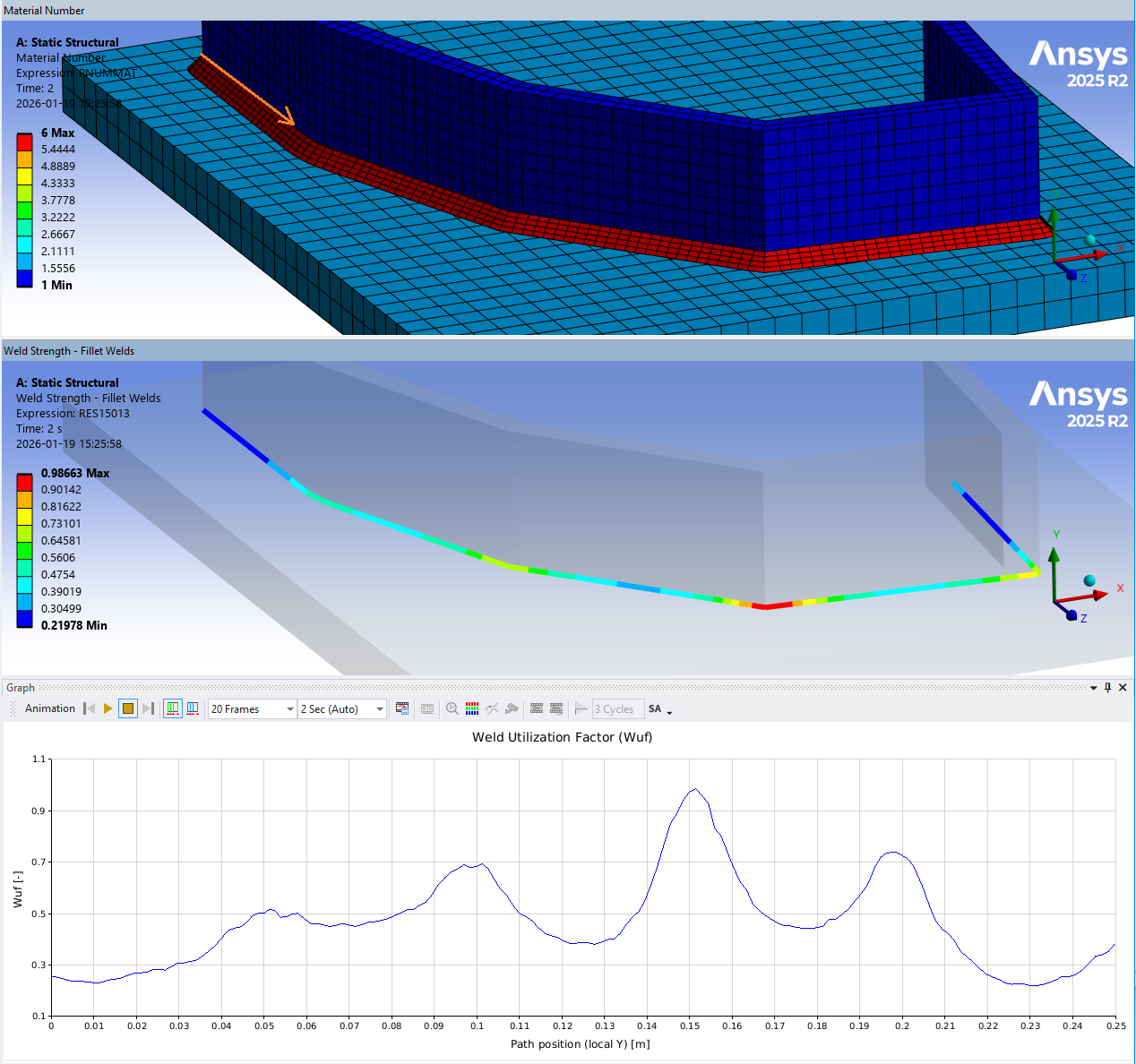
| Min thickness | Actual or calculated min needed weld throat thickness, amin to fulfil Wuf < 1 |
| Wuf | Weld Utilization Factor |
| Seqv (i) | Equivalent stress based on selected weld code, σEqv |
| Snormal (i) | Normal stress, σn (or σ﬩) |
| Tparallel | Parallel shear stress, τp (or τ‖) |
| Tnormal (i) | Normal shear stress, τn (or τ﬩) |
| Ttotal (i) | Total shear stress, τt = sqrt(τ﬩2 + τ‖2) |
| Sparallel | Parallel stress, σp (or σ‖) |
| Sbending | Bending stress, σb |
| Sstruct | Structural stress, σs |
| Stotal (i) | Total normal stress, σt = sqrt(σ﬩2 + τ﬩2) |
| Bending ratio | Bending stress ratio, Br = abs(σb)/σs |
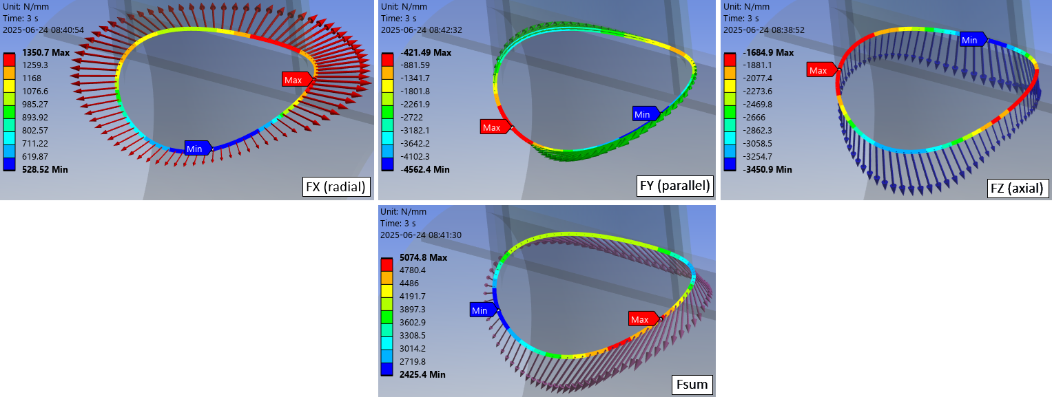
| FX (radial) | Force intensity normal (or radial) to the weld section reference face (ii) |
| FY (parallel) | Force intensity tangential (or parallel) to the weld section (ii) |
| FZ (axial) | Force intensity perpendicular (or axial) to the weld section and inplane with reference face (ii) |
| Fsum | Total force intensity along the weld section (ii) |
| MY (parallel) | Moment intensity around tangential (or parallel) weld section axis (ii) |
| MYutil | Moment utilization; ratio of MY and maximum plastic moment capacity |
| Force angle | Total force angle relative to weld section axis, Φ (used for AWS fillet calculation) |
| Weld angle | Average weld angle for the section, α |
| Result location | Relative location for critical section. 0: at reference face, 0.5: throat section, 1: target face |
(i) Stress items
The stress items are evaluated at the selected Result Location.
(ii) Force intensity
The listing of FX, FY, FZ and Fsum is of type “Force Intensity”, i.e. [N/m].
To get the total force for a weld multiply the force intensity by the section length (Sect L).
MY (parallel) is of type “Moment intensity”, i.e. [Nm/m] = [N].
Force and moment intensity for a double-sided weld is reported per weld.
The sign for stresses and forces are defined as the reaction on the reference face part.
The coordinate system can be shown by setting the Weld Group property “Show Weld Coordinate System = Yes” (or if using an older version tagging the result with “AlwaysPlotWeldcsys”).
When evaluating one of the force result items (FX, FY, FZ, Fsum, Force angle) the corresponding force vector is plotted.
If using the new option “Calculate Time History = Yes (Maximum Over Time)” the vector plot also corresponds to the max (or min) value. The vectors are visible if using the Weld Strength Setting “Plot Weld Force Vector = Yes”.
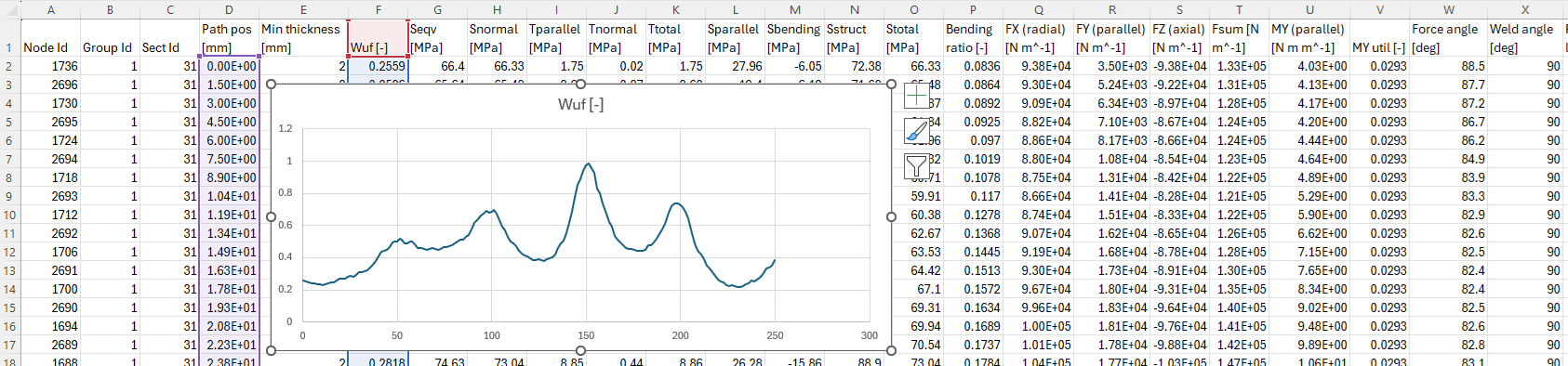
Display Graph
For a strength result with one continuous set of edges a path plot of the selected Result Item can be displayed in the Graph window. The output csv file is sorted with the “Path pos” for each group of edges.
The direction of the path is decided by the first two edges in the Geometry scoping.
Weld Utilization Factor
The default Result item is the “Weld utilization factor”, Wuf, along the weld, i.e. how much of the weld capacity that is used.
For Eurocode 3: Wuf = max(σeqv/fwEqv, σ﬩/fw﬩)
The definition of Wuf is defined in the Weld Code Editor.
The property Stress Type can be used to only consider “Positive Stress” in the Wuf calculation for the following stress items; Seqv, Sn, Sp and Ss. I.e. if the stress component is negative the corresponding Wuf = 0. This property has no impact on shear stress and related utilizations.
If the Calculate Min Thickness is set to “Yes” (or Throat thickness is set to 0) then the minimum allowed thickness along the weld is calculated. The initial thickness is set to 3 mm and stepwise increased by 1 mm until Wuf ≤ 1.0. The initial thickness and increment can be edited in the Weld Strength Settings. The min and max values can be assigned as an output parameter for parameter studies.
There is no check of the plate thickness and a recommended maximum weld thickness. The maximum allowed calculated weld thickness is limited to 99 mm. This may be edited in the Weld Strength Settings. If the calculated weld thickness is larger the thickness is set to 999 mm indicating an un-converged weld size calculation. This is an indication of a poor design in relation to the loads. If the weld thickness is much larger than the plate thickness the failure will occur in the plate instead, hence a poor design.
It is recommended to update the model with respect to the proposed weld throat thickness since the stiffness change may influence the force distribution and hence the weld evaluation as well as the nodal average that is based on the weld thickness. If using the “Add Fillet Weld” updating the model is quick and easy.
Result averaging
Eurocode 3 specifies that a load carrying weld must not be shorter than the maximum of 30 mm or 6 times the throat thickness, a. It also limits how long a weld can be to consider a uniform stress distribution. Since FEM is used that will account for a non-uniform stress distribution several averaging methods can be used to evaluate the utilization factor in order to be conservative especially regarding long welds.
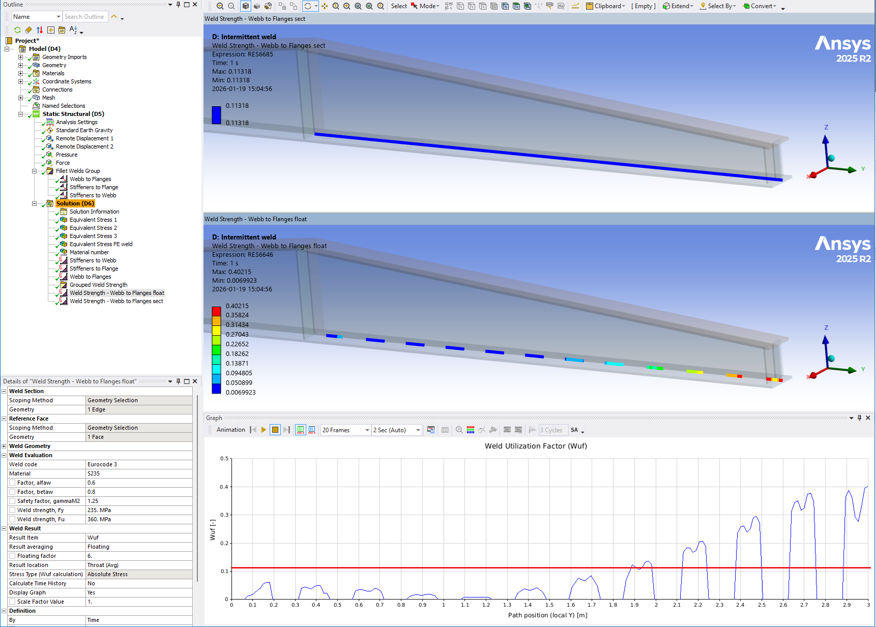
Floating average sums the section forces along the section edges based on a centered selection around each node with the length of 6·a, where a = min throat thickness. For a short single weld (length ~ 6·a) this method will give a constant result over the weld. For a longer weld the method will typically “highlight” the ends of the weld or inner points depending on how the load is applied. At a free end the effective average length will be 3·a since a centered selection is used. The Floating factor can be modified for each weld code in the Weld Code Editor. The default value for Floating factor is displayed in the result details and can easily be edited for the selected result.
Segment average splits the edge chain in virtual segments of the length “Segment length” and displays a constant value based on the summed forces from each segment. The “Segment length” can easily be edited and is automatically adjusted to fit the length of the weld. The initial length is based on the default “Floating factor”. There is an option “Condensed Segment CSV” in the Weld Strength Settings to only list one node result per segment in the result csv file.
Section (Linear) average displays a linear varying result value for each section edge based on a linearization of the total section forces. This method will correctly capture bending stress distribution in the “stiff” (in-plane) direction. See the verification case Weld Section(Linearized).
Section (Constant) average displays a constant result value for each section edge based on the total section forces. This can be very un-conservative for long welds as well as over conservative for short (length < 6·a) edge segments in a long continuous weld.
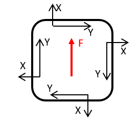
Group average displays a constant result value for all connected section edges based on the weighted sum of the individual section results in relation to the total effective group length including “Free end offset”. This is useful for plotting the total force intensity to verify with applied forces and moments etc. Group average may be misleading in the case of a closed weld loop. A global shear force (F) will result in zero parallel group force (Y) since the local coordinates X and Y are following the weld line and the force on one side will cancel out the force on the other side. The group forces or weld stresses may cancel out but the weld utilization, Wuf, is not influenced since it is based on the sum of the individual edge results and not the global forces.
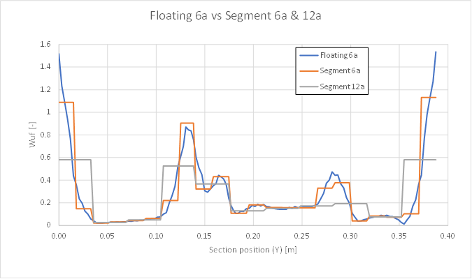
A comparison of result averaging “Floating 6a” vs. “Segment 6a” vs. “Segment 12a”
Each edge section in the weld result is grouped to find adjacent edges so that the floating, segment and group average will correctly evaluate over edge ends and short edge segments. If only selecting one or a few of the edges in a weld the floating, segment and group average are based on those edges only ignoring that the weld may be longer.
If using Weld Strength Setting “Condensed Segment CSV = Yes” the graph will not display correct if using segment average.
If using Intermittent Add Welds the Section (Constant) average will display correct weighted average results taking the Weld fraction into account.
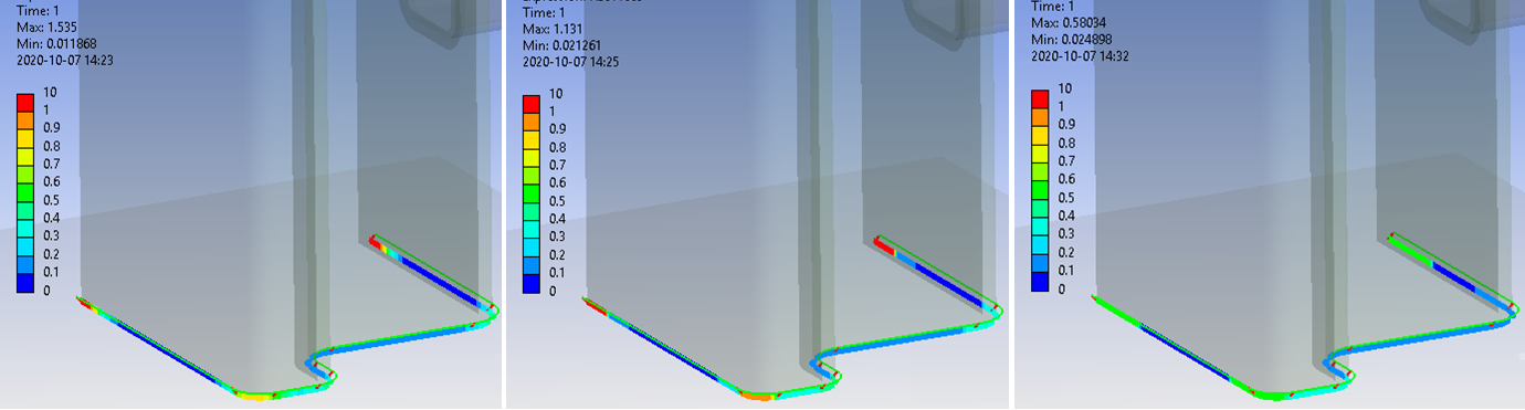
Result Location
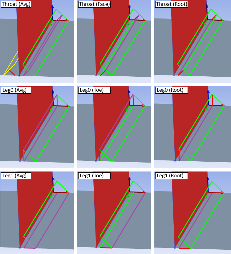
The Result Location has an updated definition starting in 2024 R2. The user can now freely select at what section (Throat/Leg0/Leg1) and location (Avg/Max/Face/Mid/Root) the weld the stresses shall be evaluated at.
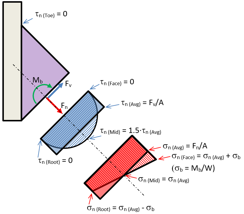
The bending stress in the section, σb, will impact normal stress, σn in location “Root”, “Toe” and “Face” .
The normal shear stress, τn , is zero at the “Root”, “Toe” and “Face” and 1.5·τn (Avg) at the “Mid”.
The Result Location will influence the following derived stresses; Equivalent stress (Seqv), Total Stress (Stotal) and Total Shear Stress (Ttotal) and the resulting Weld utilization factor (Wuf).
The default “Throat (Avg)” is a good choice in most cases when evaluating a composite section joint, e.g. an I-beam welded to a column, where local bending stress can be ignored.
The alternative “Throat (Max)” is a conservative choice for straight line single-sided fillet welds where normal force will create a bending stress due to the weld offset.
In both cases the Bending moment check will notify you if the local bending moment is higher than the maximum plastic capacity.
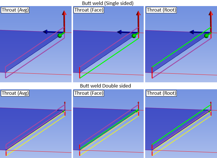
The Result Location has the following options and is visualized with purple lines in the weld graphics, see the images below.
For a double sided weld the “inactive” side is plotted with yellow lines.
| Result Location | Description |
|---|---|
| Throat (Avg) | Throat section, average stress (Default) (k1 = 0.5) |
| Throat (Max) | Throat section, max stress (k1 = 0.5) |
| Throat (Face) | Throat section, weld face stress (k1 = 0.5) |
| Throat (Mid) | Throat section, weld mid stress (k1 = 0.5) |
| Throat (Root) | Throat section, weld root stress (k1 = 0.5) |
| Leg0 (Avg) | Reference Face Leg section, average stress (k1 = 0) |
| Leg0 (Max) | Reference Face Leg section, max stress (k1 = 0) |
| Leg0 (Toe) | Reference Face Leg section, weld toe stress (k1 = 0) |
| Leg0 (Mid) | Reference Face Leg section, weld mid stress (k1 = 0) |
| Leg0 (Root) | Reference Face Leg section, weld root stress (k1 = 0) |
| Leg1 (Avg) | Target Face Leg section, average stress (k1 = 1) |
| Leg1 (Max) | Target Face Leg section, max stress (k1 = 1) |
| Leg1 (Toe) | Target Face Leg section, weld toe stress (k1 = 1) |
| Leg1 (Mid) | Target Face Leg section, weld mid stress (k1 = 1) |
| Leg1 (Root) | Target Face Leg section, weld root stress (k1 = 1) |
The parameter “k1” is the relative weld angle where k1 = 0 is at the Reference Face leg section, k1 = 0.5 is at the weld throat section and k1 = 1 is at the Target Face leg section.
The section reaction forces and stresses are defined in the coordinate systems below.
Forces and moment are defined as intensity, i.e. FX & FZ [force/length], MY, [force*length/length].
For a double-sided weld the forces and moment is given per weld seam.
The local average and bending stresses for a fillet weld are derived using the following equations.
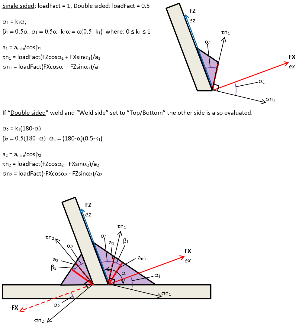
The local average stresses for a butt weld are derived using the following equations.
For a double-sided weld the forces and moment is given per weld seam.
Structural stress
One “issue” with Eurocode 3 is if bending stress over the throat section should be included in the normal stress evaluation. With the Result Location it is now possible to evaluate at both the “throat” and “leg” sections as well as using the “Avg”, “Max”, “Root”, “Mid, “Toe” or “Face” stress, hence the normal stress, Snormal, evaluated at the “Face” or “Root” corresponds to the structural stress, Sstruct, including the sign (positive: tension, negative: compression).
The structural stress is defined as; σs = σn (Avg) + σb.
The equations for normal and bending stress are defined in the figures above.
The Stress Type has in impact on how the Structural stress, σs, stress is calculated:
- If Stress Type = “Absolute Stress”: σs = abs(σn (Avg)) + abs(σb)
- If Stress Type = “Positive Stress”: σs = σn (Avg) + abs(σb)
Depending on selected “Result location” (Throat/Leg) the value of bending stress will vary since the throat thickness, a, is a function of weld angle, α.
The result items Sbending and Sstruct are not impacted of the Result Location options “Toe”, “Mid”, “Root” or “Face”.
Typically, the bending stress in the throat is a factor of two compared to the bending stress at the leg section.
- Sbamin = 6·MY/(L·amin2)
- Sbleg = 6·MY/(L·(sqrt(2)·amin)2) = 6·MY/(2·L·amin2)
- Sbamin/Sbleg = (6·MY/(L·amin2))/(6·MY/(2·L·amin2)) = 2
The bending and structural stress may be used when defining a user defined weld code.
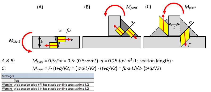
Bending moment check
Bending moment parallel to the weld may not be considered in the evaluation of the weld stress according to Eurocode 3 or AWS since the bending average stress is zero in straight sections of butt weld (A) or single sided fillet welds (B). For a shell or solid double-sided fillet weld without weld elements (C) the bending moment will result in a force pair with average weld forces that is non-zero.
A check is implemented to calculate the “Moment utilization” (MY util) that is the ratio of bending moment (MY (parallel)) and maximum plastic moment capacity, Mplast.
If the section moment is higher than Mplast a warning message notifies you to check the “MY (parallel)” and “MYutil” results items.
For a double-sided solid model with weld elements the forces and moments are derived for each weld seam individual and the moment utilization is treated as a single sided fillet weld. Tests show that the derived moment utilization is similar compared to the case without weld elements.
Random Vibration Results
When post processing a Random vibration analysis a general warning is shown from Mechanical:
“The result definitions may not be one-sigma random vibration results. Please use with caution.”
This message is show independent on the defined scale factor that defines the probability of the results.
For Random Vibration (Spectrum) and Response Spectrum analyses it is recommended to use the “mks” (SI) units when solving for best accuracy.
A Random Vibration Weld Strength result must have the Analysis Setting “Keep Modal Results = No” and “Calculate Velocity = Yes”.
A Response Spectrum Weld Strength result must have the Analysis Setting “Calculate Velocity = No” and “Calculate Acceleration = No”.
These settings are set automatically when adding a Weld Strength result to the Solution of the analysis.
Output
The Weld Strength object writes a property and result csv files to the solver files directory of the analysis. These files are used by the Worksheet Preview and Weld Report features and can easily be imported to Word or Excel.
Output csv files
Each Weld Result object also outputs a csv file named after the result object in the solver files sub folder “Weld Strength” for each result set (or time). This file contains listing of all result items for all nodes based on the selected result properties. This file can be used for plotting path results in e.g. Microsoft Excel or perform load step combinations or other post processing tasks. The results can then be plotted back using the app CSV Plot (Free on EDRMedeso GitHub pages).
The results are grouped for each chain of edges and sorted with respect to the edge connectivity and path position. The group average is identified by Node Id = 0 and Sect Id = 0. The section average is identified by Node Id = 0.
The file name ending indicates the selected time, e.g. “_Time1.0.csv” or “_MaxOverTime.csv” or “_MinOverTime.csv”.
Verification
A number of strength verification models can be downloaded from the “Demo and verification models” found in the Downloads section. A verification report can be automatically created by using the Weld Report feature. Individual results can be studied using the Worksheet Preview feature.
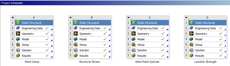
A: Weld Cases, Wuf (Eurocode 3/AISC 360-16)
The valid weld sections according to the different Types are verified in the system “Weld Cases”. The models are tested for pure shear and normal force loading. The new “Section (Linear)” average is used in the evaluation to capture the how the load orientation varies along the weld in the T-joints. The hand calculation is found in the Mechanical model as a “Comment” for each result. The solid welds are created using both “Add Fillet/Butt Weld” and CAD parts.
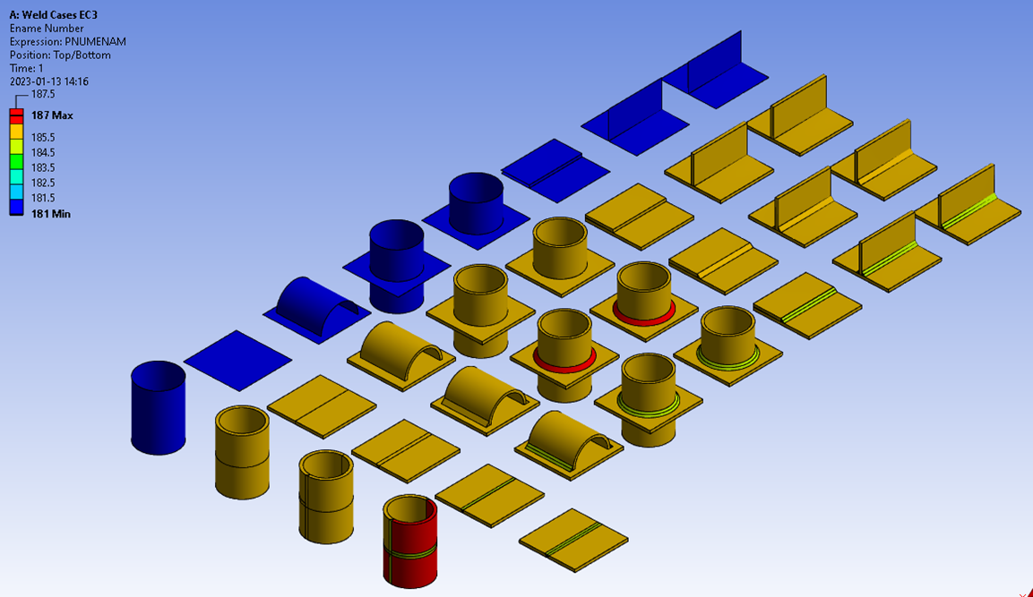
For pure shear loading all models show good agreement with hand calculation. The shell “Offset Type” may influence the results a bit especially for cylindrical faces.
For pure normal loading models with double sided solid weld elements tend to give higher weld utilization due to additional constraint forces due to the plate bending.
It is worth mentioning that only in the simplest loading cases it is possible to get agreement with hand calculation. If you have multiple welds around a bracket you cannot predict the elastic force distribution by hand, only a possible plastic limit state distribution. Also, in case of modelled welds and combined loadings constraint forces may occur in the welds that is not predicted by hand calculation, e.g. in a double-sided fillet weld with only normal loading (C2/D2) or cylindrical joints (row 4-6) you may get high normal stress due to the deformation of the structure.
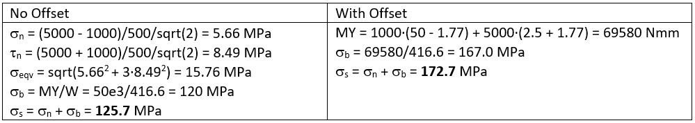
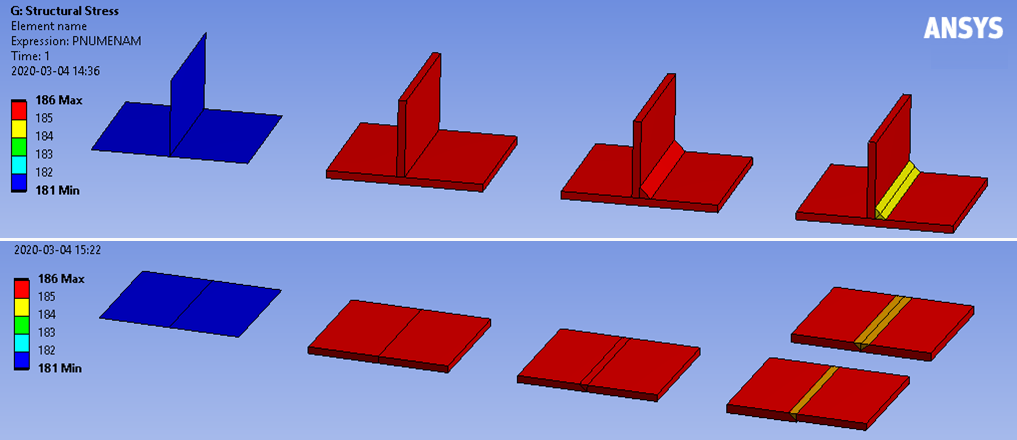
B: Structural stress
The bending and structural stress works for all types of models and is mesh size independent, see the system “Structural Stress”. If using a weld part (Model C) the structural stress is dependent of the reference face since the moment is calculated around the centroid of the selected weld reference face.
In 2024 R2 the weld offset is included automatically to compensate for the distance between the reference geometry and the weld throat section. The “Result location” influences the bending stress calculation a lot, see the comment in the section Structural stress.
The test load is an axial force, FZ = 5000 N, and an out of plane bending force, FX = 1000 N. The throat thickness, a = 5 mm, and weld length, l = 100 mm, height, h = 50 mm. Bending moment, MY = FX·h = 1000·50 = 50·103 Nmm. Weld area; A = 100·5 = 500 mm2. Weld sect; W = l·a2/6 = 100·52/6 = 416.6 mm3
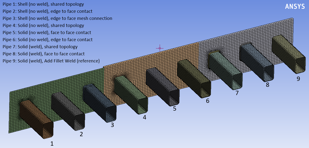
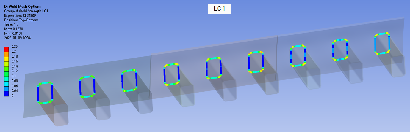
C: Comparison weld mesh methods
This demo illustrates how different meshing methods using shell or solid elements and representing the weld with or without elements will influence the results, see the system “Weld Mesh Options”. This demo is also updated for 2026 R1 to reflect the improved floating average method that smoothens the weld forces and removes unrealistic “spikes” in the results.
The shell models have the thickness offset inwards. The solid models use solid shell (SOLSH190) except for the weld part itself. The models are created in ascending complexity/quality where model 9 is the reference model using the “Add Fillet Weld” with 4 elements over the throat section.
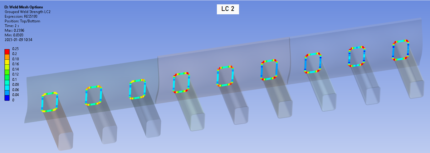
A bending load adds shear and normal forces on the welds. The three pipes with welds (7 - 9) has slightly lower deformation since the welds adds stiffness to the structure. The other pipes have identical deformation and hence stiffness. A second load step adds a pure axial load to the pipes.

The Weld Strength result shows that the pipes without welds have almost identical results and the three pipes with welds have slightly different results.
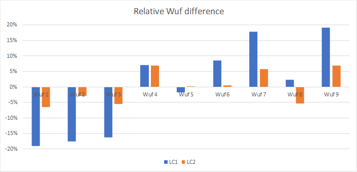
The following bar plot shows the average Wuf along the weld for all models. The bending load case, LC1, has a variation of approximately ±15%. The shell models (Pipe 1-3) have lower Wuf than the solid models in general. The solid model with welds using shared topology (Pipe 7) has lower Wuf than the other solid models. The solid models with weld elements using contacts (Pipe 8-9) have slightly higher Wuf than the models without welds.
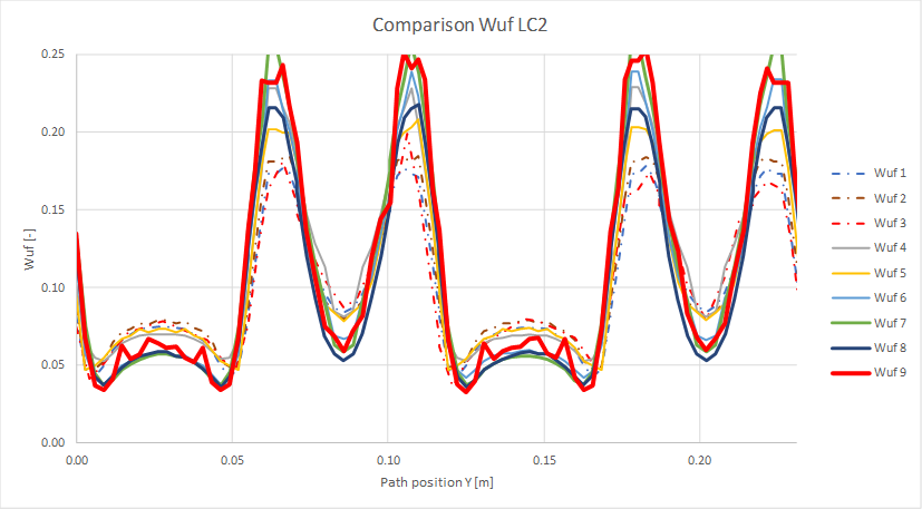
For the tension load case, LC2, the variation in Wuf is smaller ±6% and no clear trend is visible.
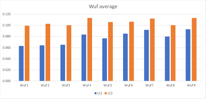
The floating average of weld utilization factor, Wuf, for each pipe is plotted in the graphs below.
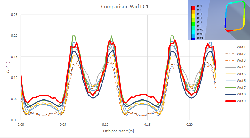
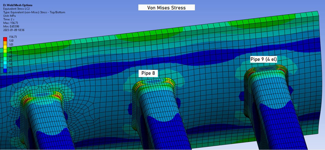
Shell models without weld elements (Pipe 1-3) has almost identical Wuf results independent of the joint method but may differ depending on load case compared to the reference model. Shell models without weld elements don’t have that much constraint forces that explains the lower Wuf in LC1 compared to the reference model with weld elements. A solid multi-body part model with weld elements (Pipe 7) tends to under predict Wuf, see Bonded contact vs. multi-body.
The difference between Pipe 8 and Pipe 9 (reference) is that the section forces for the reference model are extracted from the throat contact section and not the contact between the pipe and weld as for Pipe 8. Also note that for a model with weld parts the result might differ depending on what side of the weld that is used as the reference side. It is possible to use the planar faces of the weld in contact to the plate as well as the faces in contact to the pipe.
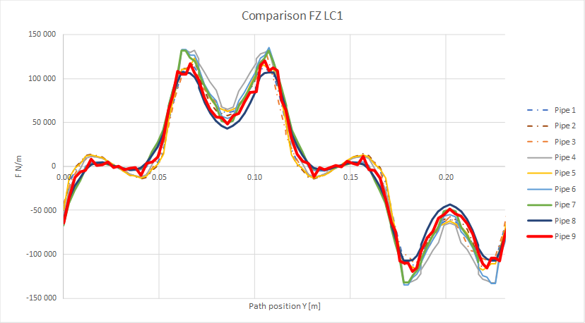
Looking at the axial force intensity (FZ) all models have very similar results except Pipe 7, again highlighting that shared topology on a weld part must be avoided and instead use the Add Welds.

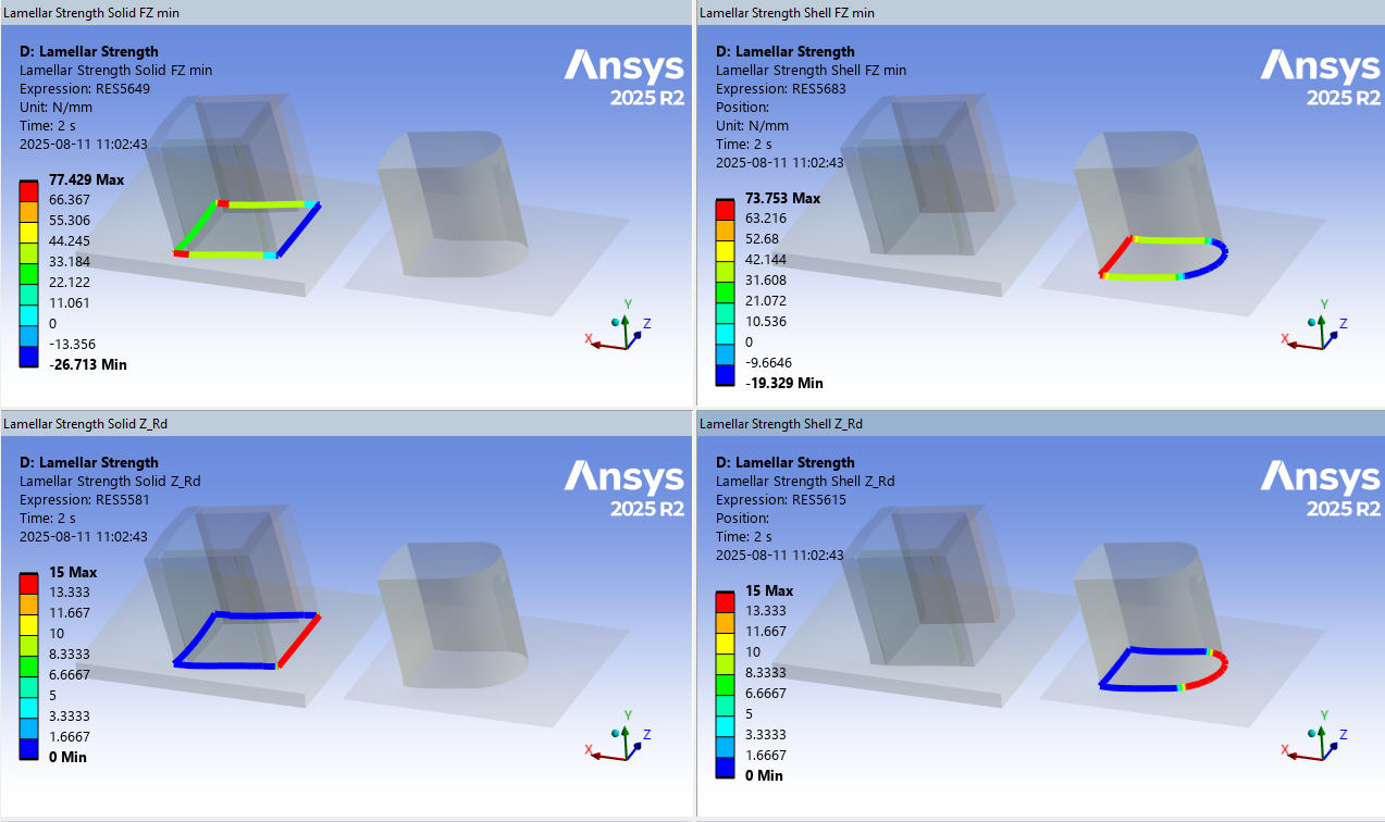
D: Lamellar Strength
The lamellar strength case tests the influence of an always compressive load in a weld section compared to a load that changing between tension and compression.
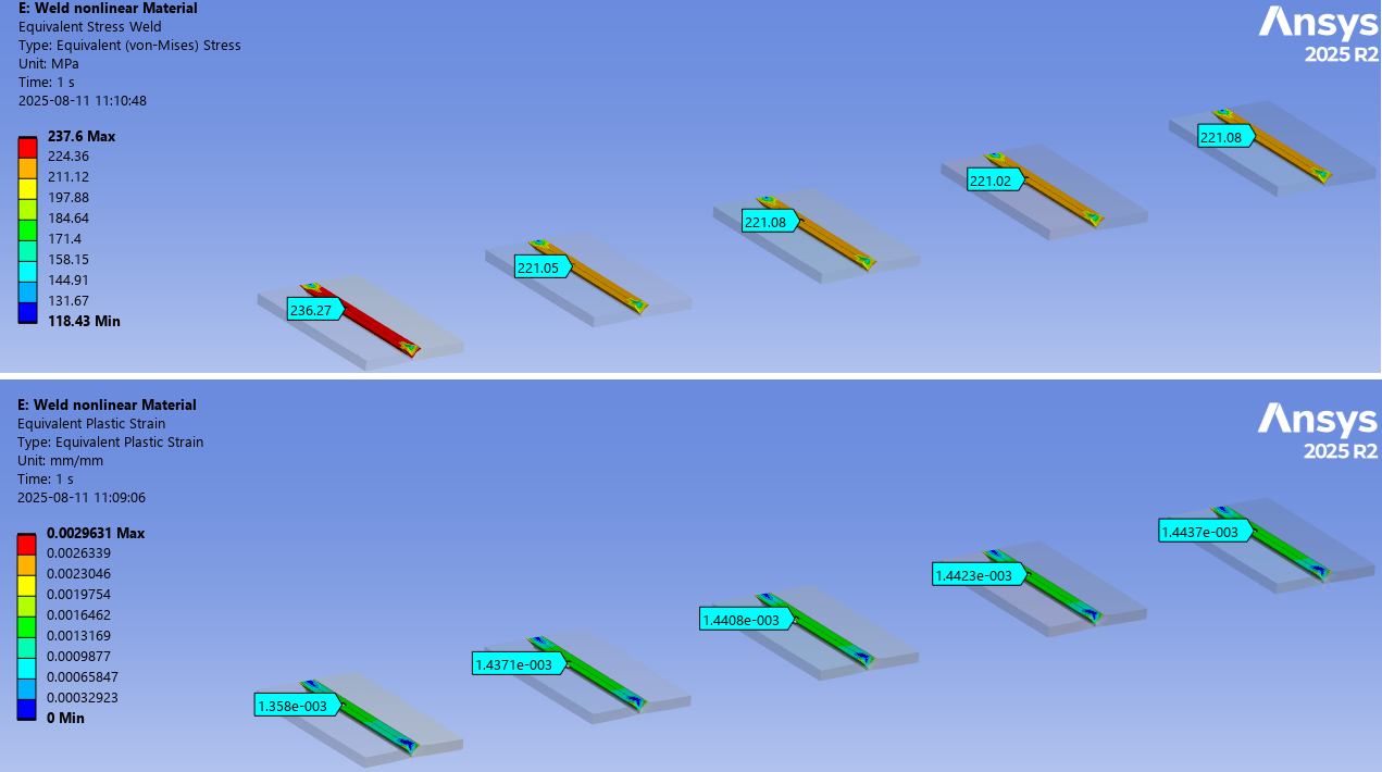
E: Non-linear Material
The non-linear default weld material for “Add Welds” is tested and compared with “Engineering Data” material.
Weld Toolkit material “S235-BISO” has only one temperature data point why Seqv = 235 MPa.
The four other S235 materials from Engineering Data has two temperature points. Ry(T=22) = 235 MPa Ry(T=200) = 200 MPa Interpolated yield stress: Ry(T=100) = 220 MPa
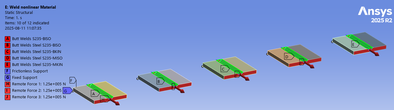
Approximately 1.4e-3 plastic strain and 1000 MPa tangent modulus gives 1.4 MPa hardening in the weld.
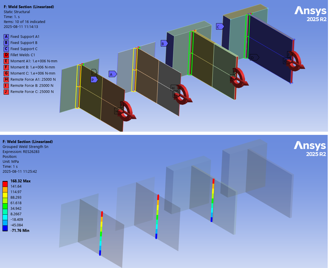
F: Weld Section (Linearized)
The weld strength result averaging “Section (linearized)” is verified for nodal and element results in this system. The Group Strength/Fatigue Result output is also tested.

 Weld Strength Shell
The “Fillet Weld Strength Shell” and “Butt Weld Strength Shell” is used to post process welds in shell models.
The first difference compared to the standard Fillet Weld Strength and Butt Weld Strength result is that the results are plotted on the elements attached to the weld section edge, see left part of figure below. This allows multiple welds connected to the same edge to be evaluated at the same time. For large welded structures with many cruciform joints all welds can then be evaluated at once since multiple reference faces can be selected for all weld section edges.
The second difference is result averaging that has only two options “Element” and “Section”. Since element size in large shell models is much greater than the weld throat thickness a floating or segment average does not make sense. The “Group” option is only meaningful if a single weld line is selected.
Except for these two changes all other aspects of the result properties works in the same way.
A shell model may also be evaluated using the original “Weld Strength” result, see the demo system “Cruciform Joint” in “WeldToolkit-StrengthDemos_X.wbpz”.
+ Full Penetration Weld Strength
Starting in 2025 R1 it is possible create a “full penetration weld” by combining a Fillet Weld Strength result from an Add Fillet Weld with a Butt Weld Strength result using a Virtual Butt Weld that is using the same Weld Section edges and Reference Faces. The parts must be connected by contacts, otherwise the Add Fillet Weld is not possible to add.
The two results can be grouped using Grouped Weld Strength to provide the maximum utilization from the two objects.

 Clear selected weld result files
When a model is solved all existing temporary weld nodal coordinate and force listings are deleted (weld_n_.lis, weld_f_.lis, etc.). This command does only clear the cached force data in the RAM memory for the selected result object and is only meaningful to use in the case if the weld contact or shared face is “thick” in relation to the weld throat thickness (t > 5*amin), see the Shared face for solid models above for details.
If selecting the “Solution” object all weld results cached data is cleared.
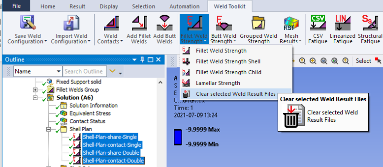
The weld result object is not cleared, and the result summary listing and csv file are kept.