 Design Codes
Table of contents
 General Information
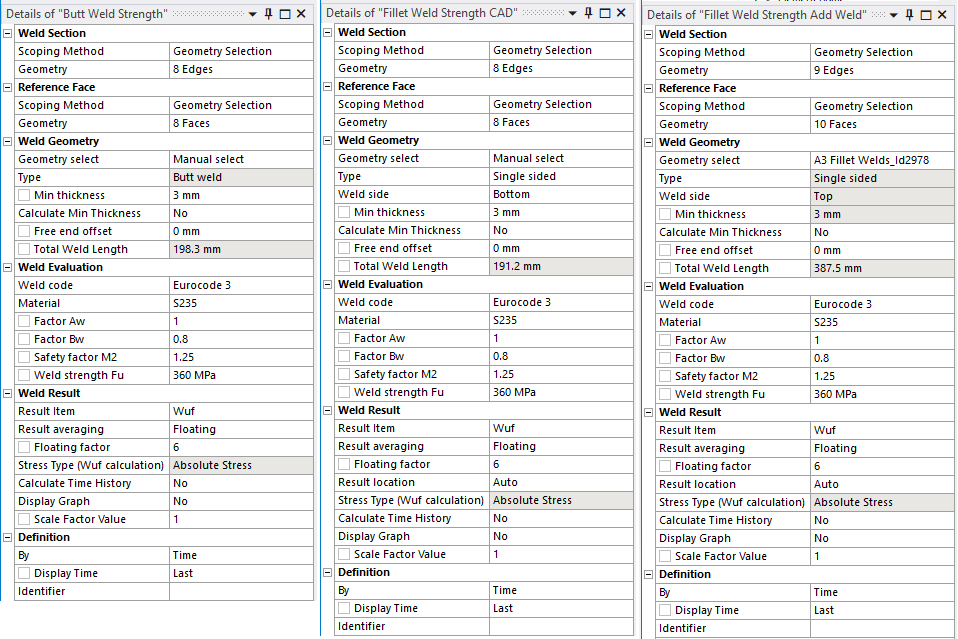
The Eurocode 3 and AISC 360-16 implementation has been reworked and the interface in Fillet/Butt Weld Strength result is updated in the 2021R1 release. When selecting “Eurocode 3” (or “AISC 360-16”) in the Weld code field additional properties are displayed.
Weld Evaluation Properties
The used Engineering Data material name of the selected Add Fillet Weld is matched with the Material for the selected Weld Code.
| Weld Evaluation | |
|---|---|
| Weld code | “Weld Code” (Default “Eurocode 3”) (i) |
| Material | Select material class. (Sets Fy, Fu, αw, βw and γM2) (Default “S235”) |
| Factor, Aw | Correlation factor αw > 0 (Default 0.6) |
| Factor, Bw | Correlation factor βw > 0 (Default 0.8) |
| Safety factor, gammaM2 | Partial safety factor γM2 > 0 (Default 1.25) |
| Yield Strength, Fy | Nominal yield tensile strength fy ≥ 0 (Default 0 MPa) |
| Ultimate Strength, Fu | Nominal ultimate tensile strength fu > 0 (Default 360 MPa) |
| Filler Strength, FuFM | Nominal ultimate tensile strength filler material fu,FM ≥ 0 (Default 0 MPa) |
(i) Weld Code
The available Weld Codes and default Weld Code are defined in the Weld Code Editor.
Currently available codes are:
- Eurocode 3 (Default)
- Eurocode 3 Simplified
- Eurocode 3 Full penetration butt welds
- AWS Groove Complete Penetration
- AWS Groove Partial Penetration
- AWS Fillet
- DNV Fatigue (2.3.4) (Used for Structural Stress Fatigue)
Weld Stress
The strength evaluation is based on the “Directional Method” where nominal stress components are derived from the weld section forces and moments based on the selected Result averaging to create a uniform or smooth stress distribution.
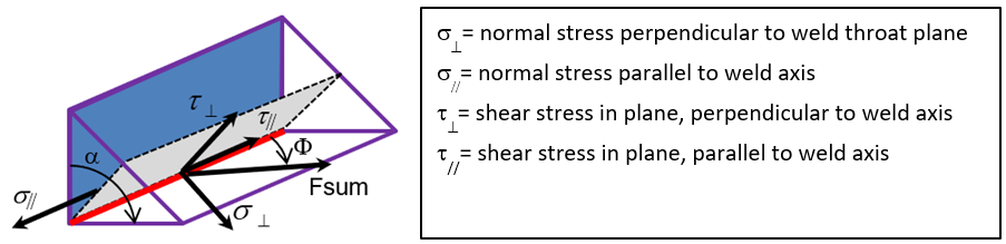
In addition to the stress components in the figure above (used by Eurocode 3) the additional components are also available to use.
- σb = MY/W bending stress (around weld axis), W = L·a2/6 (L: local weld length, a: throat thickness)
- σs = σ﬩ + σb structural stress (normal plus bending stress)
- σtot = sqrt(σ﬩2 + τ﬩2) total normal stress perpendicular to weld axis
- τtot = sqrt(τ‖2 + τ﬩2) total shear stress in the plane
- σeqv = f(σ, τ) equivalent stress (function of stress components defined in the selected Weld code)
- Φ = Angle between weld total force, Fsum, and the red weld axis (in radians). Can be used to define fw.Rd
For each weld stress component a corresponding Weld Design Resistance can be defined.
Validity of the result
Please pay attention to chapter 4 “Basis of design” in EN 1993-1-8:2024 Eurocode 3.
It is the user’s responsibility to ensure that the FE-model, chosen method, input values and results obtained by this application is suitable for his/her intended purpose, e.g. to evaluate according to a selected joint category and to apply load safety factors according to use case, e.g. operational vs. ultimate limit.
Also see the new standard: EN 1993-1-14:2025 Eurocode 3: “Design of steel structures - Part 1-14: Design assisted by finite element analysis”.
For user defined weld codes, it is also the user’s responsibility to verify the validity of the method, e.g. by using test and verification models together with hand calculation.
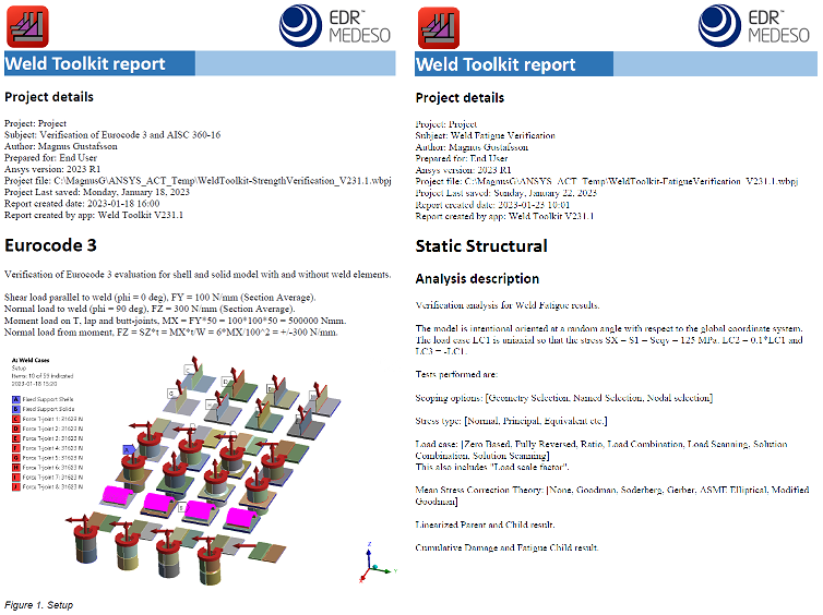
Verification models for strength and fatigue are included in the Downloads section under “Demo and verification models” where the different codes and methods are tested and compared with the expected values. Solve the model and click Weld Report to get the verification report.
 Eurocode 3
Reference to sections and equations from Eurocode 3 1993-1-8:2024 are shown in brackets or italics.
The “Eurocode 3” uses “Directional method” (6.5.3.2).
To achieve a uniform distribution of stress in the weld seam the Result averaging is set to “Floating” with a floating factor of “6”. This value is based on that the minimum length according to Eurocode 3 for a load carrying weld is 6·a (or 30 mm).
The “Eurocode 3 Simplified” uses “Simplified method for design resistance of fillet weld” (6.5.3.3).
In Eurocode 3 simplified it is stated that: “design resistance of a fillet weld may be assumed to be adequate if, at every point along its length, the resultant of all the forces per unit length transmitted by the weld satisfy the following criterion.”
To achieve a stress “at every point” in the weld seam the Result averaging is set to “Floating” with a floating factor of “2”.
The design strength fw.eqv is updated to account for filler material strength fu.FM if larger than zero.
The “Eurocode 3 Full penetration butt welds” (6.7.1) for welds in steel grades equal to or higher than S460 uses a modified expression for “fw.Sn”. It is not stated in the code if “fw.eqv” also applies but that is assumed.
General Eurocode 3 recommendations
- Weldable structural steels conforming to EN 1993-1-1:2022.
- The plate thickness must be larger than or equal to 3 mm.
- The weld filler material yield and ultimate limit must be equal or better than the base material.
- If using steel grade equal to or higher than S460 the filler material may be undermatching or overmatching.
- Load carrying fillet welds must be longer than 30 mm or 6 times the throat thickness (a-value).
- Quality level C according to EN ISO 25817 is usually required.
- Lamellar tearing should be avoided (EN 1993-1-10:2025), see Lamellar Strength result.
- The angle between the plates in a fillet weld must be in the range of 60° – 120°.
Material
The Material is defined in the Weld Settings Weld Code Editor.
The values are from: “Table 6.1: Correlation factor βw for fillet welds” and from
“Table 6.2 — Ultimate strength of filler material fu,FM and modified correlation factor βw,mod”.
The yield strength, fy, and factor αw is not used by Eurocode 3.
The partial safety factor γM2 is 1.25 for welds (Table 2.1).
| Material | fy [MPa] | fu [MPa] | fu,FM [MPa] | αw | βw | γM2 |
|---|---|---|---|---|---|---|
| S235 | (235) | 360 | 0 | (0.6) | 0.80 | 1.25 |
| S275 | (275) | 390 | 0 | (0.6) | 0.85 | 1.25 |
| S355 | (355) | 490 | 0 | (0.6) | 0.90 | 1.25 |
| S420 | (420) | 510 | 0 | (0.6) | 0.88 | 1.25 |
| S460 | (460) | 540 | 0 | (0.6) | 0.85 | 1.25 |
| S500 | (500) | 580 | 0 | (0.6) | 0.90 | 1.25 |
| S550 | (550) | 600 | 0 | (0.6) | 0.95 | 1.25 |
| S620 | (620) | 700 | 0 | (0.6) | 1.05 | 1.25 |
| S690 | (690) | 770 | 0 | (0.6) | 1.10 | 1.25 |
| G42 | (0) | 0 | 500 | (0.6) | 0.89 | 1.25 |
| G46 | (0) | 0 | 530 | (0.6) | 0.85 | 1.25 |
| G69 | (0) | 0 | 770 | (0.6) | 1.09 | 1.25 |
| G69 | (0) | 0 | 940 | (0.6) | 1.19 | 1.25 |
The material table is updated according to “Table 5.1: Nominal values of yield strength fy and ulitimate strength fu…” EN 1993-1-1:2022.
Also note that different grades or thickness of the same material may have different ultimate strength. Make sure to adjust fu if needed.
Weld Design Resistance
Eurocode 3
- Equivalent stress resistance: feqv,Rd = fu/(βw·γM2) (6.1)
- Equivalent stress resistance (≥S460): feqv,Rd = (0.25·fu + 0.75·fu,FM)/(βw·γM2) (6.2)
- Normal stress resistance: fn,Rd = 0.9·fu/γM2 (6.1)
Eurocode 3 Simplified
- Equivalent stress resistance: feqv,Rd = fu/(sqrt(3)·βw·γM2) (6.5)
- Equivalent stress resistance (≥S460): feqv,Rd = (0.25·fu + 0.75·fu,FM)/(sqrt(3)·βw·γM2) (6.6)
Eurocode 3 Full penetration butt welds
- Equivalent stress resistance (≥S460): feqv,Rd = (0.25·fu + 0.75·fu,FM)/(βw·γM2) (6.2)
- Normal stress resistance: fn,Rd = -(0.85·0.9·fu + 0.15·fu,FM)/γM2_ (6.7)
Weld Design Stress
The used Load Factor, γL, is to be defined and verified by the user depending on application and use case. If the applied loads in the model include the Load Factor then “Scale Factor Value = 1.0” should be used. If the loads are applied with nominal values then set the recommended γL as the “Scale Factor Value” in the weld result object.
Eurocode 3 and Full penetration butt welds
- Design Equivalent stress, feqv.Ed = σeqv = sqrt(σ﬩2 + 3·(τ﬩2 + τ‖2))
- Design Normal stress, fn.Ed = σn = abs(σ﬩)
It is not directly stated if the absolute value or only the positive (tension) value of the normal stress should be considered in the equation above when calculating the weld utilization factor, Wuf. The default behavior for the app has always been to use Stress Type = “Absolute Stress”. The Stress Type used is now shown as a read-only property in the weld strength result details. The default value and read only status can med modified in the Weld Code Editor for each weld code, see more in the section for “Wuf calculation”.
Eurocode 3 Simplified
- Design Equivalent stress, feqv.Ed = σeqv = sqrt(σ﬩2 + τ﬩2 + τ‖2)
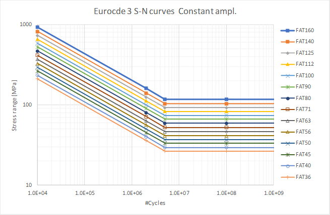
Eurocode 3 S-N Curves
All Eurocode 3 S-N curves uses Ncutoff = 1e8.
The Eurocode 3 S-N curves are defined in the FAT Class Editor. See section “B.3.1 Stresses from fatigue actions” and “Figure B.1 - Definition of hot spot type “a”, “b” and “c””.
- Figure 8.2: Fatigue strength curves for normal stress ranges, Constant amplitude.
Figure B.3 Hot-Spot Type A & B FAT90, FAT100, FAT112
Slope m2 = 1e6 is used from knee point at Nc = 5e5 up to N = 1e8.
-
Figure 8.2: Fatigue strength curves for normal stress ranges, Variable amplitude.
Figure B.3 Hot-Spot Type A & B FAT90, FAT100, FAT112

-
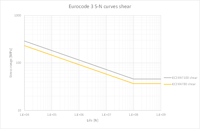
Figure 8.4: Fatigue strength curves for shear stress ranges.
-
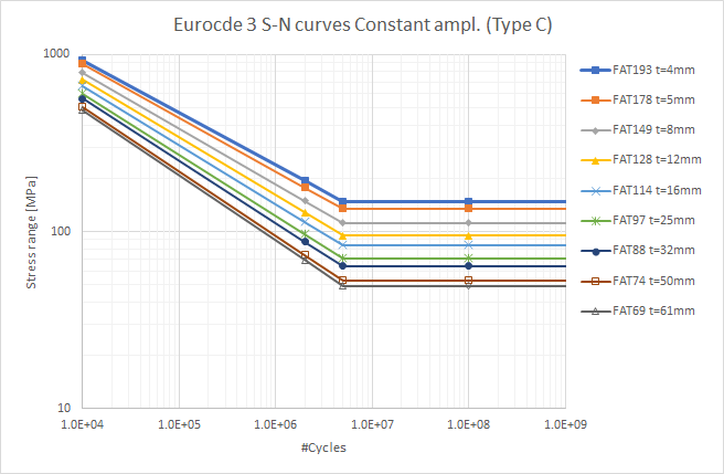
Figure B.4: Fatigue strength curves for Hot-Spot stress ranges, Constant amplitude. Type C
-
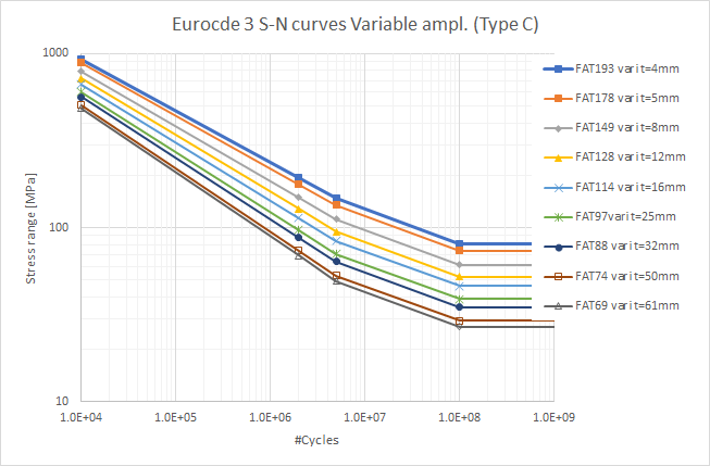
Figure B.4: Fatigue strength curves for Hot-Spot stress ranges, Variable amplitude. Type C
Effective notch curves (Section C.3.1 Figure C.2) are not included. “FAT225” (for principal stress) is same as “IIW FAT225 R1 steel” and “FAT200” (for von Mises stress) can be user defined if needed.
“HFMI treatment” curves (Section F.4.1 Figure F.1) are not included but can easily be added as a user defined curve if needed.
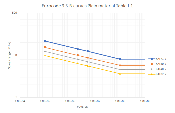
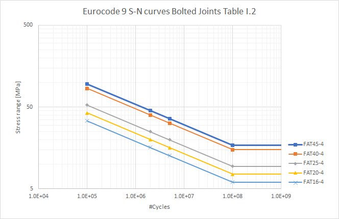
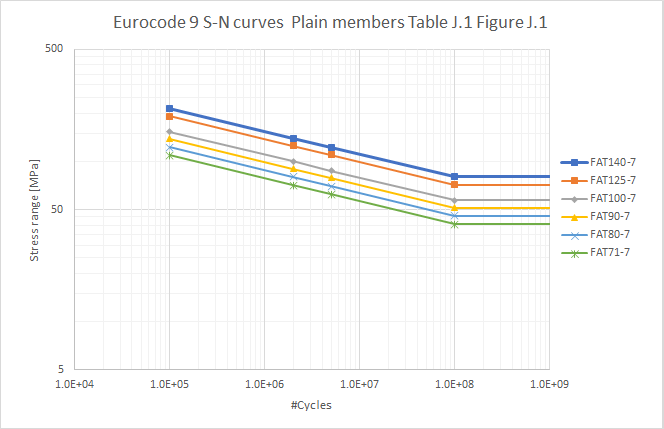
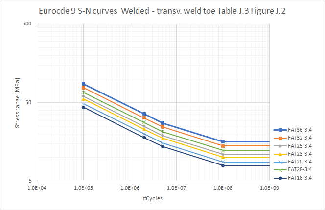
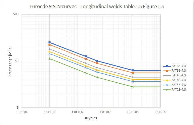
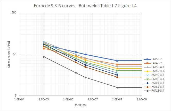
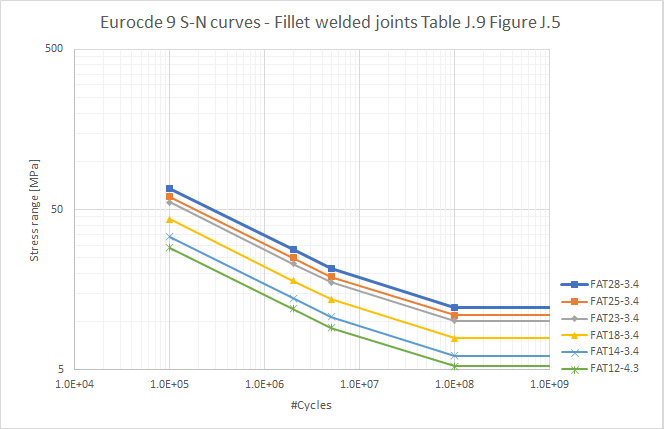
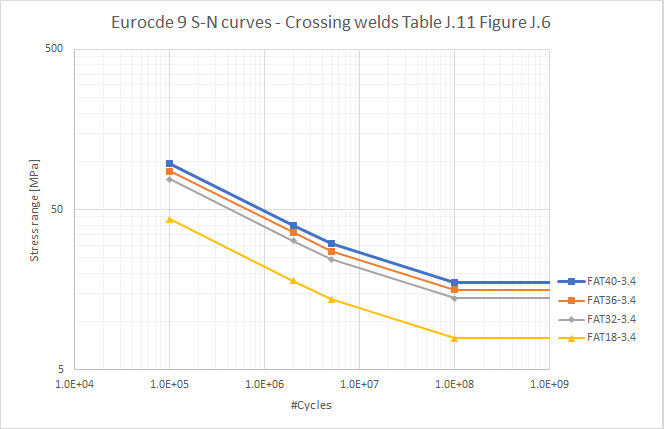
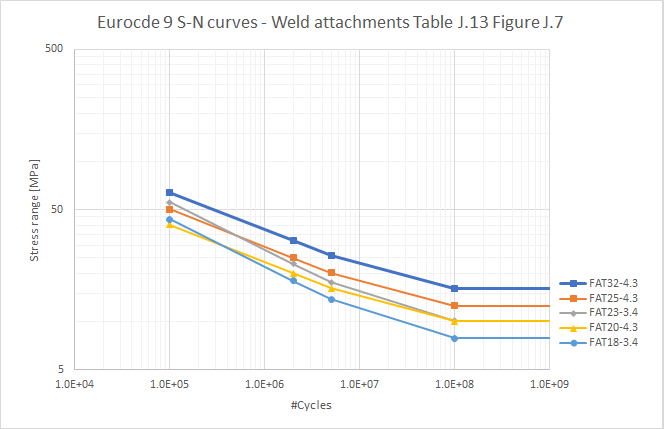
Eurocode 9 S-N Curves
All Eurocode 9 S-N curves uses Ncutoff = 1e8.
The FAT Class base name is printed in between brackets.
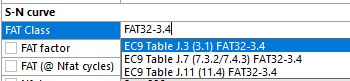
The Eurocode 9 FAT Class list differs between 1999-1-3:2007 and 1999-1-3:2023 regarding the “Table number”.
The same S-N curve may appear in multiple tables, e.g. “EC9 Table J.3 (3.1) FAT32-3.4” and “EC9 Table J.7 (7.3.2/7.4.3) FAT32-3.4”.
Always search for the curve by typing the “FAT” name in the FAT Class list box to filter the selection.
-
Table I.1: Fatigue strength curves for plain material. (EC9 Table I.1*)
-
Table I.2: Fatigue strength curves for bolted joints. (EC9 Table I.2*)
-
Table J.1/Figure J.1: Fatigue strength curves for plain members. (EC9 Table J.1*)
-Table J.3/Figure J.2 Fatigue strength curves for members with welded attachments, transverse weld toe. (EC9 Table J.3*)
-
Table J.5/Figure J.3 Fatigue strength curves for members with longitudinal welds. (EC9 Table J.5*)
-
Table J.7/Figure J.4 Fatigue strength curves for butt welded joints between members. (EC9 Table J.7*)
-
Table J.9/Figure J.5 Fatigue strength curves for fillet welded joints between members. (EC9 Table J.9*)
-
Table J.11/Figure J.6 Fatigue strength curves for crossing welds on built-up beams. (EC9 Table J.11*)
-
Table J.13/Figure J.7 Fatigue strength curves for attachments on on built-up beams. (EC9 Table J.13*)
 AISC 360-16
The method is based on AWS D1.1/AISC 360-16 Table J2.5 and defines the weld capacity for butt (groove) welds and fillet welds.
The base metal shear strength, is assumed to be 60% (αv) of the ultimate strength, fu.
The design strength, φ·Rn (LRFD) and the allowable strength, Rn/Ω (ASD) of welded joints shall be the lower value of the base material strength, Rn = FnBM·ABM (J2-2), and the weld material strength, Rn = Fnw·Awe (J2-3).
It is assumed that the weld nominal strength, Fnw, is equal or lower than the base material nominal strength, FnBM. It is also assumed that the weld effective area, Awe is equal or lower than the base material cross section area, ABM. With these assumptions it is only necessary to evaluate the weld. If this is not the case you also need to evaluate the base material.
Material Class
The Material defined in the Weld Settings Weld Code Editor is used to select if “Allowable Strength Design” (ASD) or “Load and Resistance Factor Design” (LRFD) is used to calculate the design strength, fw.Rd. The factors φ and Ω for each weld type are converted to βw and γM2.
fw.Rd = αw·fu/(βw·γM2)
where
fu = FEXX = electrode minimum strength
αw = Shear strength factor
βw = Correlation factor (used to scale γM2 for “Grove Partial”)
γM2 = Joint resistance partial safety factor = Ω (ASD) or = 1/φ (LRFD)
γL = Load factor
The resulting design resistance differ between ASD and LRFD. In ASD all safety factors are applied on the material resulting in an “allowable strength” value and loads are taken with their nominal value. In LRDF material safety factors are applied on the material resulting in a “design strength” value in combination with a load factor, γL (similar to Eurocode 3). The LRDF method is designed to give the same Wuf as ASD by using γL = φ·Ω = 0.75·2.0 = 1.5.
| Material | fy [MPa] | fu [MPa] | αw | βw | γM2 | γL |
|---|---|---|---|---|---|---|
| Groove Complete (ASD) | 235 | 360 | 0.60 | 1.0 | 2.0 | 1.0 |
| Groove Complete (LRFD) | 235 | 360 | 0.60 | 1.0 | 1.3333 | 1.5 |
| Groove Partial (ASD) | 235 | 360 | 0.60 | 0.94 | 2.0 | 1.0 |
| Groove Partial (LRFD) | 235 | 360 | 0.60 | 0.9375 | 1.3333 | 1.5 |
| Fillet (ASD) | 235 | 360 | 0.60 | 1.0 | 2.0 | 1.0 |
| Fillet (LRFD) | 235 | 360 | 0.60 | 1.0 | 1.3333 | 1.5 |
Weld Design Resistance
Groove welds, Complete Joint Penetration
Strength of the joint is controlled by the base metal (φ = 0.75, Ω = 2.00).
- Tension and compression stress normal to weld axis:
ASD: fn.Rd = Fnw/Ω = FnBM/2.0 = fu/γM2
LRFD: fn.Rd = φ·Fnw = 0.75·FnBM = fu/γM2 - Shear stress:
ASD: fv.Rd = Fvw/Ω = FvBM/2.0 = αv·fu/γM2
LRFD: fv.Rd = φ·Fvw = 0.75·FvBM = αv·fu/γM2
Groove welds, Partial Joint Penetration
Strength of the joint is controlled by the weld metal.
-
Tension (and compression) stress normal to weld axis (φ = 0.80, Ω = 1.88):
ASD: fn.Rd = Fnw/Ω = 0.60·FEXX/1.88 = αv·fu/(βw·γM2)
LRFD: fn.Rd = φ·Fnw = 0.80·0.60·FEXX = αv·fu/(βw·γM2) -
Shear stress (φ = 0.75, Ω = 2.00):
ASD: fv.Rd = Fvw/Ω = 0.60·FEXX/2.00 = αv·fu/γM2
LRFD: fv.Rd = φ·Fvw = 0.75·0.60·FEXX = αv·fu/γM2
Fillet welds
For fillet welds loaded in-plane through the center of gravity the available strength is permitted to be determined accounting for a directional strength increase if strain compatibility of the various weld elements is considered.
- Equivalent stress through the center of gravity (φ = 0.75, Ω = 2.00).
Fnw = 0.60·FEXX·(1 + 0.5·sin1.5Θ) (J2-5)
where Θ = angle of loading measured from the weld longitudinal axis.
For each weld the available design resistance is evaluated as a function of the weld strength, fu, and the load angle, Θ.
f(fu, Θ) = fu·(1 + 0.5·sin1.5Θ)
ASD: feqv.Rd = Fnw/Ω = 0.60·f(fu, Θ)/2.00 = αv·f(fu, Θ)/γM2
LRFD: feqv.Rd = φ·Fnw = 0.75·0.60·f(fu, Θ) = αv·f(fu, Θ)/γM2
Weld Design Stress
The used Load Factor, γL, is to be defined and verified by the user depending on application and use case. If the applied loads in the model include the Load Factor then “Scale Factor Value = 1.0” should be used.
ASD: γL = 1.0, LRFD: γL = 1.5
- Design Normal stress, fn.Ed = γL·abs(σ﬩) ≤ fn.Rd
- Design shear stress, fv.Ed = γL·sqrt(τ﬩2 + τ‖2) ≤ fv.Rd
- Design Equivalent stress, feqv.Ed = γL·sqrt(σ﬩2 + τ﬩2 + τ‖2) ≤ feqv.Rd
The “Design Equivalent stress” is calculated as the vector sum of the weld section stresses.
 DNV-RP-C203
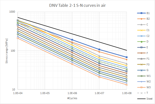
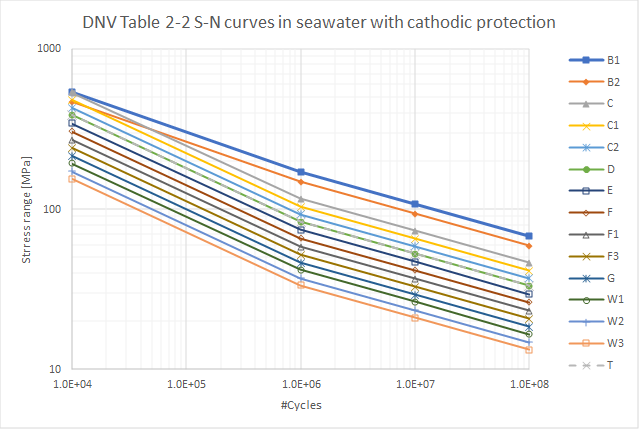
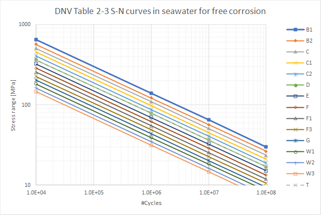
DNV-RP-C203 S-N Curves
DNV does not specify a cutoff limit, Ncutoff = 1e10 cycles is used.
The FAT Class base name is printed in between brackets.
-
DNV Table 2-1 S-N curves in air. (DNV T.2-1*)
-
DNV Table 2-2 S-N curves in seawater with cathodic protection. (DNV T.2-2*)
-
DNV Table 2-3 S-N curves in seawater for free corrosion. (DNV T.2-3*)
 IIW Recommendations for fatigue
IIW does not specify a cutoff limit, Ncutoff = 1e10 cycles is used.
The FAT Class base name is printed in between brackets.
IIW S-N Curves - Nominal & Hot-Spot Method (Steel)
- Fatigue resistance S-N curves for steel, normal stress, very high cycles application, Fig 3.2. (IIW FAT* steel)
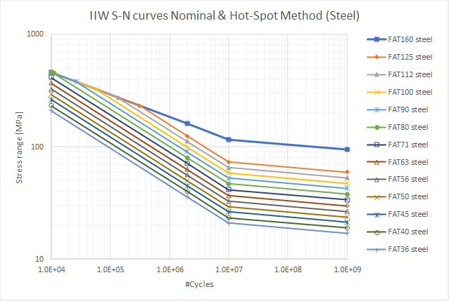
IIW has also S-N curves defined for “Standard application” Fig. 3.1.
You may use these curves by setting “FAT Class = User defined” and set “Slope m2 = 1e6”.
- Modified resistance S-N curves of steel for Palmgren-Miner summation, Fig 4.1. (IIW FAT* steel vari)

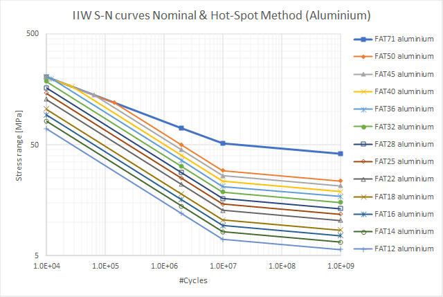
IIW S-N curves – Nominal & Hot-Spot Method (Aluminum)
-
Fatigue resistance S-N curves for aluminum, normal stress, Fig 3.3. (IIW FAT* aluminum)
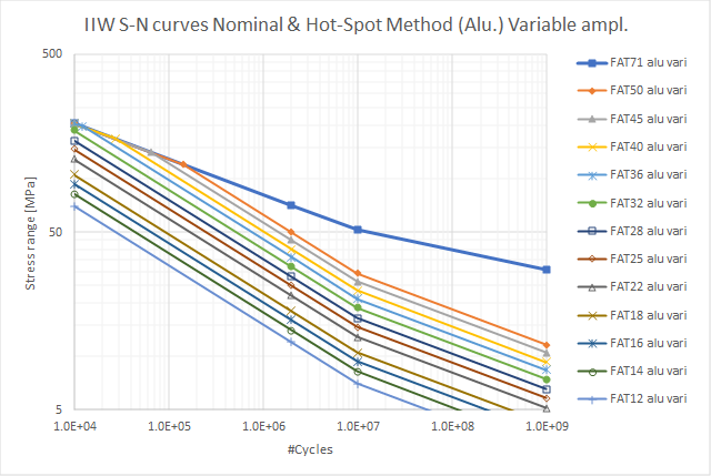
-
Modified resistance S-N curves of aluminum for Palmgren-Miner summation, Fig 4.2. (IIW FAT* alu vari)
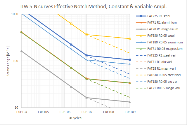
IIW S-N curves – Effective Notch
- Fatigue resistance S-N curves of steel, aluminum and magnesium. (IIW FAT* R1), (IIW FAT* R0.05)
 User
User
User defined weld strength design codes can be created with the Weld Code Editor in Weld Settings.