 Open Preferences (Legacy)
Table of contents
About
The “Open Preference” is the legacy way of customizing the default properties. Starting in V231.5 this feature and documentation is replaced by the new Weld Settings object.
Click one of the preference buttons to edit the corresponding settings if you want to make permanent changes in the file. The preference files are located in the app installation folder (%appdata%\Ansys\v2XY\ACT\extensions\WeldToolkit_V2XY.Z). The changes are applied next time you open Workbench or click “New Project”.
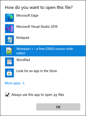
You may have to assign a default action for file type “.py” in Windows so it opens in a text editor and not tries to run the file in a Python terminal.
Weld Strength Preferences
Weld Strength General Preferences
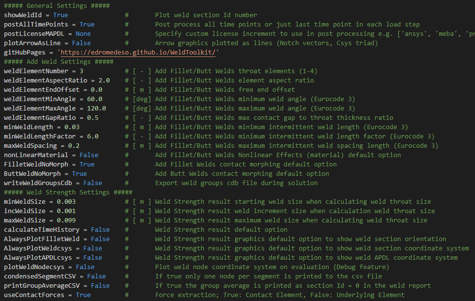
A few general parameters may be edited by the user in the preference file to control the “Add Fillet Weld” creation and “Weld Strength result” sizing of welds. The result export to txt and csv file can also be controlled. The default value for “Calculate Time History” has changed to “No”. This can be controlled by the new parameter “calculateTimeHistory”. When welds are post processed the MAPDL solver is used and a custom license increment can be used instead of the default one, “postLicenseMAPDL”.

Weld Strength Code definition
The weld strength evaluation including material definition, safety factors, criteria etc. is defined in the preference file. Weld Toolkit has an API (Application Programming Interface) that allows the creation of additional weld codes by the user. The existing code “Eurocode 3” is included and can be used as an example for additional codes.
The weld codes are defined using a Python dictionary where the user can add key words and expressions to define the material parameters, dimensional weld strength and weld stress used in the evaluation.
Weld stress parameters
The available weld stress parameters when evaluating is listed in the beginning.

Weld codes
The default code and available codes are defined in the beginning of the weld code dictionary “weldCodes”.

A new weld code is defined by adding the lines below. The name “Eurocode 3” is displayed in the Weld code list box in the Weld Strength result object. The “floatingFactor” average length factor must also be defined.

Materials
The available weld material classes can be modified in the “material” block. This block is optional.

Strength Criteria
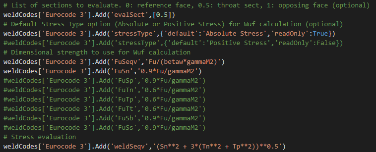
evalSect: The list of weld sections to evaluate are defined by the property “evalSect”. The default is “[0.5]”, i.e. the throat section only. To include both leg sections extend the list to: “[0, 0.5, 1]”
stressType: In the normal and structural stress evaluation the option “stressType” can be “Absolute Stress” or “Positive Stress”, i.e. to only consider “positive” (tension) stress or the “absolute” (tension or compression) stress.
Fu: The dimensional strength is defined by adding lines for any of FuSeqv, FuSn, FuSp, FuTn,FuTp, FuTt, FuSb, FuSs.
weldSeqv: If FuSeqv is defined the “weldSeqv” must also be defined as a function of the weld section stress parameters.
FuSeqv can also use the weld force angle phi as an input parameter (see “AWS Fillet”).

Eurocode 3 uses only FuSeqv and FuSn hence the “#” to blank the definition of the other.
The weldSeqv parameter can be used to define a dimensionless expression that combines weld section stress parameters and design resistance parameters.

This equation can be implemented in a weld code by defining the expressions according to the image below.
To manage different display units the unit conversion parameter “convFu” must be included in the “FuSeqv” and “weldSeqv” expression, otherwise the result item “Seqv” (utilization) will only be displayed correct if using SI (m, kg) as display unit.

Weld Fatigue General Preferences
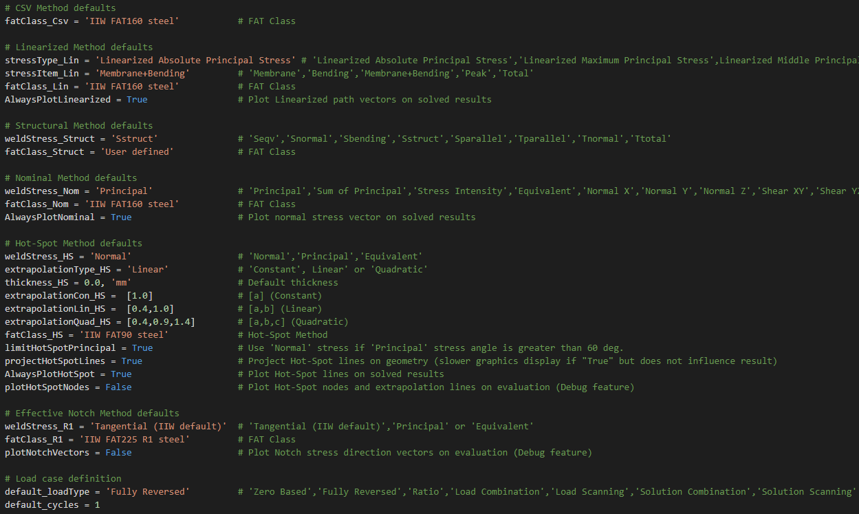
Default properties for the fatigue methods such as S-N Curve and load case defined here. These properties are used when adding a new result to the model tree. This can be used to define default settings for a specific design code.

S-N Curves
Custom S-N curves can be added to the app using the API found below “# FAT Class Dictionary”. Curves for IIW, DNV, EC3 and EC9 are included and shown in the Design Codes section. The “FAT factor”, fatFact, property can be defined in each curve, e.g. to scale the curve for different failure probabilities.

One additional feature when defining a S-N curve in the preference file is the possibility to include a second break point, N0, and a corresponding slope, m0 and a cutoff limit Ncutoff. This is used for IIW and DNV to “limit” a curve with the base material curve.

