
 Add Welds
Table of contents
About
The Add Fillet Welds and Add Butt Welds are load features where weld seams are created and placed in a group folder in the current Structural, Modal or Thermal analysis. The Welds are constructed of linear SOLID185 or quadratic SOLID186 brick elements. Bonded contacts at the weld legs uses “projection-based method” and contact morphing for robust contact results, see CONTA174 in Ansys help for more information.
The Welds can also be added in a thermal analysis using linear SOLID278 or quadraticSOLID279 elements. The temperatures will be mapped to the structure if using the “Imported Loads”.
The Modal analysis must have “Pre-Stress Environment = None” for the weld group to be added.
Usage
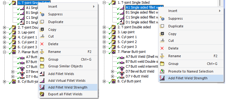
Click on “Add Fillet Welds” (or “Add Butt Welds”) in the toolbar inserts the Fillet Welds Group folder in the current static analysis and creates the first Fillet Welds load object.
To add additional welds right click on the Fillet Welds Group folder and select “Add Fillet Welds” or click on the “Add Fillet Welds” in the toolbar again. You can also use “Duplicate” on an existing Weld and modify the properties. You can add multiple “Welds Groups” using the context action “Insert>Fillet Welds Group” on the the selected “Analysis”.
Inputs to define the Fillet/Butt Welds are:
| Weld Section | |
|---|---|
| Scoping Method | Geometry Selection (Default)/Named Selection (i) |
| Geometry | Weld section edges of a solid model along the weld seam root. |
| Reference Face | |
| Scoping Method | Geometry Selection (Default)/Named Selection |
| Geometry | Reference Faces connected to the Weld Section edges (ii) |
| Weld Geometry | |
| Geometry select | Add Fillet/Butt Welds (Read only) |
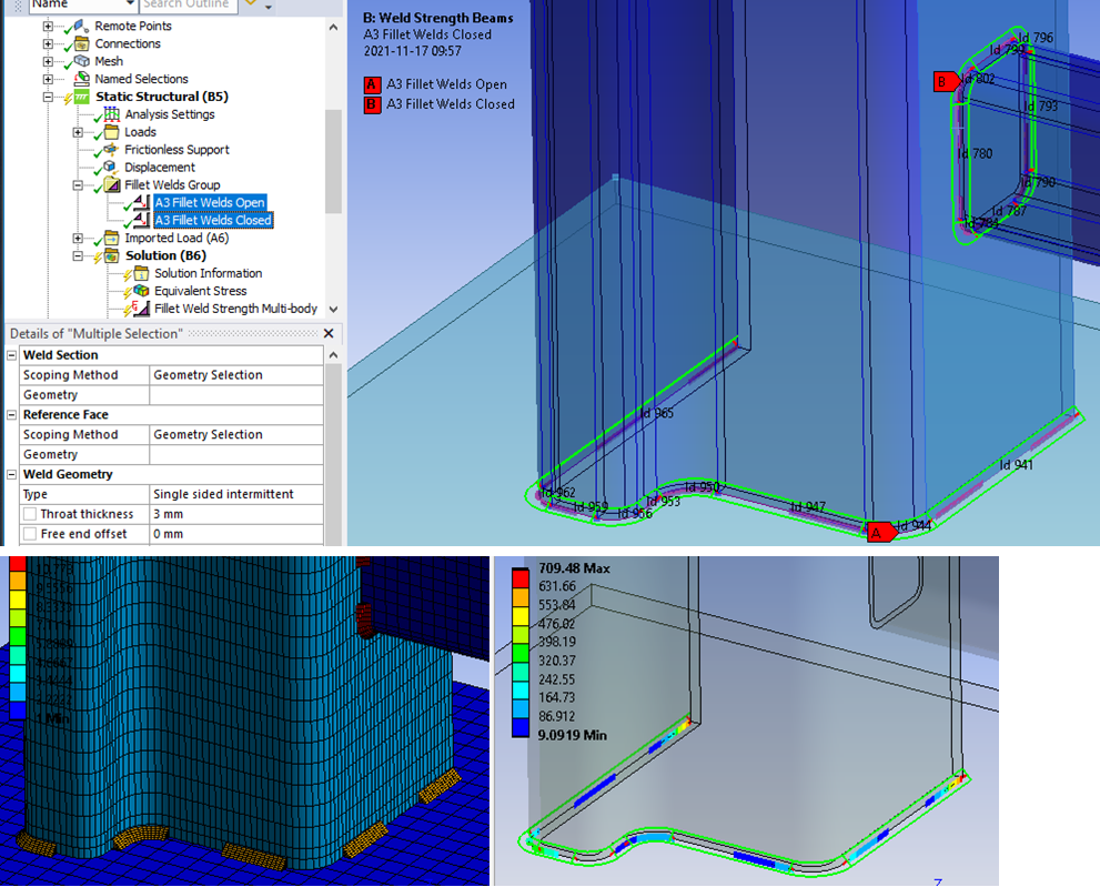
| Type | Single sided (Default)/Single sided intermittent/V-Butt Weld/Bevel Butt Weld/V-Butt intermittent/Bevel Butt intermittent (iii) |
| Throat thickness | Weld throat thickness, a < 100 mm (Default 3 mm *) |
| Free end offset | Offset of start and end for open weld seams. |
| Section Length (iii) | Read only property of Section length, Lsection, used to help decide the weld fraction. |
| Weld fraction (iii) | Ratio of Total Weld Length to Section Length, Lweld/Lsection . |
| Number of Welds (iii) | Total number of weld segments for the selected set of weld sections. |
| Weld Length (iii) | Individual weld segment length. |
| Weld Spacing (iii) | Length between each weld segment. |
| Material | Select material from “Engineering Data” or app default materials. |
| Display Advanced Options | Yes/No. If “Yes” properties marked (v) are displayed. |
| Nonlinear Effects (v) | Yes/No. Use plasticity models defined in the selected material (default ‘No’ *) (iv). |
| Element Order (v) | Linear/Quadratic. Weld element order (default ‘Quadratic’ *). |
| Throat elements (v) | Number of elements (1-4) over throat thickness (default 2 *). |
| Min weld angle (v) | Limit angle when creating weld elements (default 60 deg *) |
| Max weld angle (v) | Limit angle when creating weld elements (default 120 deg *) |
| Aspect Ratio (v) | Weld elements aspect ratio. 1 <= aspect <= 20 (default 2 *). |
| Contact adjustment (v) | Yes (Default)/No. Contact adjustment to morph weld leg contacts to target faces. (*) |
| Export Weld Line (v) | None/SCDM Point curve (text)/DM 3D curve (text). Weld Geometry Export file format for in SpaceClaim Direct Modeler or Design Modeler format. |
| Total Weld Length | Length of the weld seam Lweld to help estimate welding time and cost (Read only). |
| Total Weld Mass | Read only property of total weld mass to help estimate weld material cost. |
(*) Default values
Default values for these properties are defined in the Weld Settings.
New default values is set for Element Order = ‘Quadratic’ and Throat elements = 2 to reduce the error for large bending moment in combination with perpendicular forces.
(i) Scoping Method
The manual “Geometry Selection” can be converted to a “Named Selection” using the context action “Promote to Named Selection”.
(ii) Reference Face
If selecting additional faces these are used as target faces only and plotted in turquoise color. See Reference Face below for examples.
(iii) Intermittent
Selecting Type = “… intermittent” displays these properties.
(iv) Material
The following material properties (and corresponding MAPDL MP Lab) are supported: Young’s Modulus (EX), Poisson’s Ratio (NUXY), Density (DENS), Coefficient of Thermal Expansion (ALPX), Thermal Conductivity, (KXX), Specific Heat (C), Isotropic Hardening (BISO & MISO), Kinematic Hardening (BKIN, KINH). If orthotropic properties are defined the X component is automatically used (EX, NUXY, ALPX & KXX).
When selecting “Nonlinear Effects = Yes” the following settings are defined automatic: “Element Order = Quadratic” and “Throat elements = 3”.
When selecting “Nonlinear Effects = No” the following setting are defined automatic: “Element Order = Linear”.
The Element Order and Throat elements may be modified after changing Nonlinear Effects.
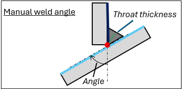
(v) Manual Fillet Weld Angle
By setting “Min weld angle = Max weld angle” the fillet weld angle is set constant in relation to the Reference Face. Use this option if the weld part does not align with the angle of the target part like in the figure below.
A property file is also written to the solver files directory that is used by the Weld Report feature.
Weld Section
This is the location where the weld seam root is placed. The edge cannot be a shared edge in a multi-body part. Also make sure that there are no bonded or no separation contacts defined between the solid parts (from “Auto Detection”). It is recommended to use solid shell mesh method on thin solids. The edge mesh sizing should not be larger than 5*Throat thickness.
Weld Section Mesh Sizing
A mesh “Sizing” can be added using the context action “Add Section Edge Sizing” for an individual Weld object or the parent Weld Group.
If updating the Weld Section scoping or Throat thickness for the weld object you may use “Add Section Edge Sizing” again to apply the changes.
The created mesh sizing object may be edited if needed, e.g. to change the “Element Size” or “Number of Divisions”.
The resulting edge sizing, L = Throat thickness*Aspect ratio.
To delete the mesh object use the context action “Delete Section Edge Sizing” (or delete individual objects in the model tree).
The “Add Section Edge Sizing” is also available for Virtual Welds.
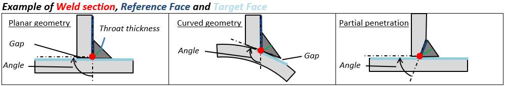
Reference Face
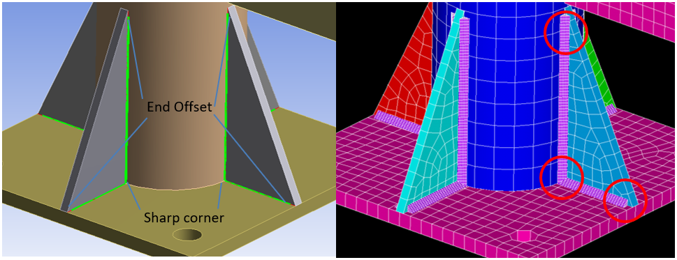
The weld geometry will follow Planar or Curved geometry. The weld Angle is derived from the angle between the Reference face and the opposite face connected to the Weld section edge. The property Min weld angle (weldElementMinAngle *) and Max weld angle (weldElementMaxAngle *) will control if a weld can be placed.
In the picture below only parts of the full edge length fulfil the angle criteria. An error message is shown if no weld elements are created for a group of edges.
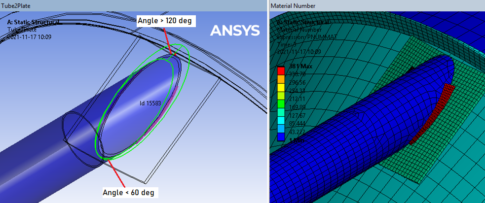
The Target face is automatically detected from solid element nodes within a bounding box with padding size Gapmax around the weld contact face nodes. A small Gap between the parts is also allowed as the weld mesh is morphed onto the target faces using contact adjustment. The maximum gap size, Gapmax, is defined as a fraction (default 50%) of the Throat thickness a; Gapmax = Weld Gap ratio·a (*). This value is also used as the pinball radius, “PINB”, for the weld contact.
The reference face for one section edge cannot be the “target” face for another section edge in the case of defining multiple weld chains in the same weld object. Separate the edge chains so they do not belong to parts for the “target” face. Defining welds for multiple flange parts to one common target face in one Fillet Weld object is OK.
If additional faces not connected to any section edge are selected these are used as target face only. For complex thin-walled geometry this is recommended to avoid that contacts are created on both sides of the target plate.
Partial penetration welds can be defined by using the “chamfer” face as the reference face.
The Throat thickness, a, is always defined from the section edge out to the free weld surface for each node along the weld line, see example of pipe connection in the section “Visualization of weld mesh and weld stress results”.
Weld Geometry
Weld Mesh
The mesh generation can sweep around sharp corners and align the node planes. 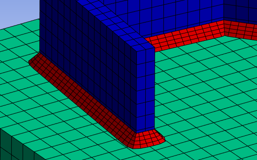
For an outside corner angle greater than 90 degrees the mesh is split.
For an inside corner angle smaller than 135 degrees the mesh is split.
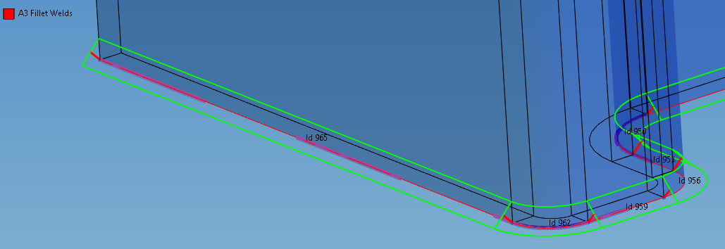
For a weld seam with free ends (an open chain) the start and end of the weld can be offset from the start and end vertex using the property “Free end offset”, see the weld corners in the picture below. Also note the inner corner where the weld mesh is splited.
The default value of “Free end offset” is defined in the Add Weld Settings.
The weld seam is also checked for negative volume elements that may occur if the throat thickness is greater than the section edge curvature at an inner radius.
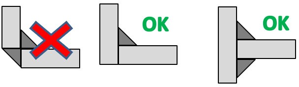
Combining “Add fillet weld” with standard contacts between the connected parts may cause contact constraint forces resulting in un-realistic weld results. For the same reason creating fillet welds on both the inside and outside corner is not recommended. It is “impossible” to weld when only the corners touch.
Intermittent weld
Intermittent welds will be correctly placed on open and closed edge chains. An open chain will always have a weld segment in the beginning and the end of the edge chain. A closed chain will have evenly spaced weld segments. You may also mix open and closed edge chains in one weld object. The first edge in a chain selection is used to define the start vertex and the second edge is used to define the direction of the section path.
Intermittent weld parameters
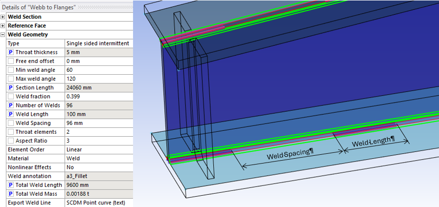
For intermittent welds the parameters “Weld fraction”, “Number of Welds”, “Weld Length” and “Weld Spacing” have relations to each other. When updating one parameter the others are updated automatically as well. Assigning a new Weld fraction will recalculate the number of welds needed based on the current Weld Length and then adjust to the actual Total Weld Length and Section Length. The resulting Weld fraction is then re-calculated based on the discrete number of welds from Total Weld Length and Section Length (Example below: Weld Fraction = 96·0.1/24.06 = 0.399).
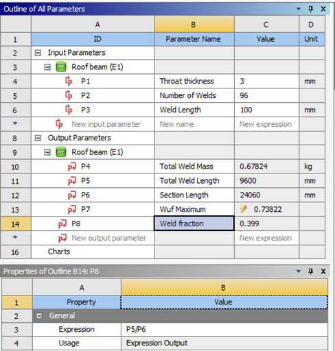
Also note that the minimum “Weld Length” and the maximum “Weld Spacing” are defined in the Add Weld Settings. If using Design Explorer to analyze different weld parameters use “Throat thickness”, “Number of Welds” and “Weld Length” as input parameters and “Total Weld Length”, “Section Length” and “Total Weld Mass” as output parameters. The resulting weld fraction can be derived as a new output parameter using an expression for “Total Weld Length” divided by “Section Length”; “P5/P6”.
Visualization of weld mesh
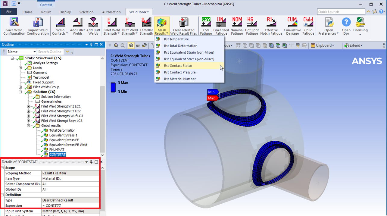
The mesh (and results) can be visualized using a “User Defined Result” with Scoping Method: “Result File Item”. See the section Mesh Results on how to plot.
In case of complex geometry with curvature and gaps the weld contact status can be verified by a “Rst Contact Status”. The contact status values have the following meaning; 0: Open far, 1: Open near, 2: Closed sliding, 3: Closed sticking (Bonded).
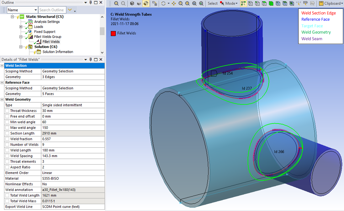
Graphics
A graphic representation is created once valid inputs are given and the model is meshed.
- Weld Section edges are plotted as red lines.
- Reference Faces are plotted in dark blue.
- Optional Target Faces are plotted in turquoise.
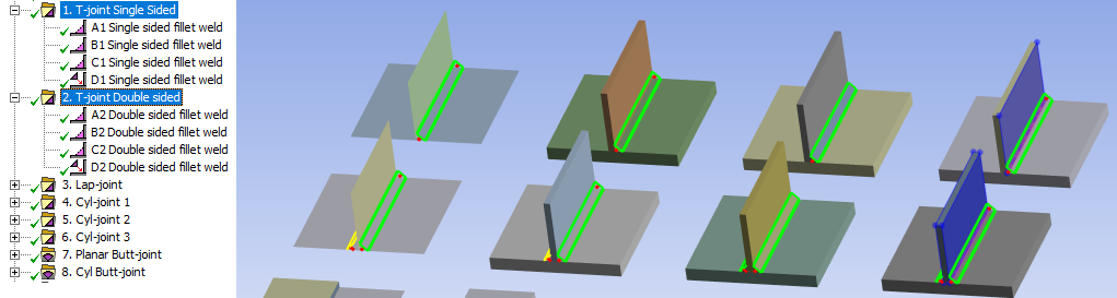
- Weld geometry wire frame is plotted in green lines.
- Weld throat thickness is plotted with a red line.
- Weld seam is plotted with a thick purple line on top of the Weld Section.
The weld section Id number is printed at the center of each section edge and is used in the result tables.
In case of invalid scoping only the Id numbers causing the error are plotted.
The printing of Id number can be turned on/off in the General Settings.
Contact adjustment
By default the CNCHECK,MORPH option is used to align the weld mesh contact nodes with the target elements for improved contact convergence.
If you have planar geometry and no gaps or for some other reason don’t want to morph the weld contact nodes to the target face you may set this option to “No”. The default value for the new welds is defined in the Add Weld Settings.
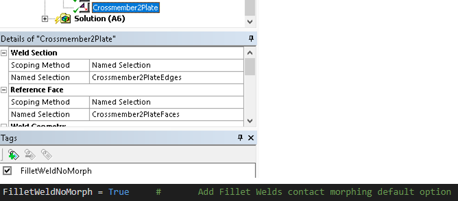
In versions before 2025 R1 the Tag “FilletWeldNoMorph” was used on the weld object to exclude it from morphing.
Debugging tips
If the green lines that define the weld geometry is not displayed at the expected location the surface geometry quality may be poor.
Solution: Try to simplify the geometry in SpaceClaim/Discovery, e.g. replace a face with a new planar or cylindrical face.
If the lines are “translated” or “scaled” the saved geometry information has been corrupted.
Solution: Open SpaceClaim/Discovery and “cut and paste everything” (CTRL+A, CTRL+X, CTRL+V) and then close. This trick forces a geometry update that usually will resolve any graphical issues.
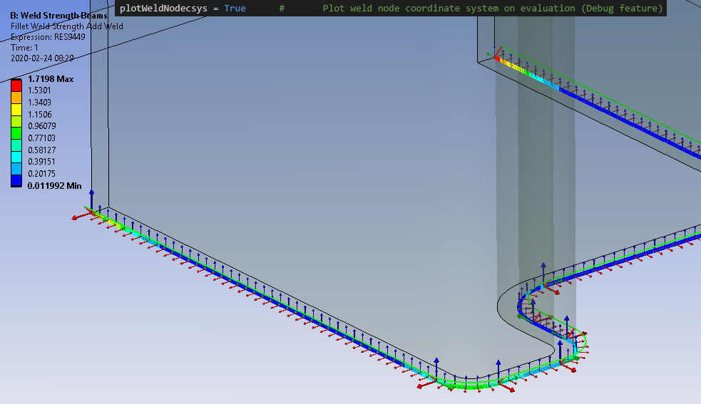
There is a debug option in the Weld Strength Settings that will plot the weld nodes coordinate system when evaluating a weld result. The triad has the same orientation as the “Weld Csys” plotted at the beginning of each edge.
In case the model does not solve you may open the model in MAPDL to review the mesh before solving by adding a MAPDL system to the “Setup” component of your analysis and the select “Edit in Mechanical APDL…”.
This allows you to inspect the weld mesh and element quality etc. prior to solving. There is a component (Named Selection) named “FILLETWELDGROUPELEM” that contains all fillet welds created by the app.

 Weld Geometry Export
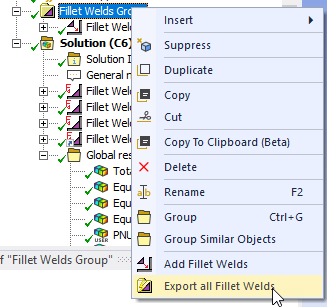
The fillet weld mesh and weld lines can be exported prior to solving the model using the context menu option “Export all Fillet Welds” on the “Fillet Welds Group”. The mesh is written to the ANSYS cdb file “FilletWeldGroupExport.cdb” in the “Solver Files Directory” subfolder “WeldStrength”. This weld mesh will not be morphed onto the reference and target faces and allows for easy conversion to solids using the steps below.
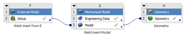
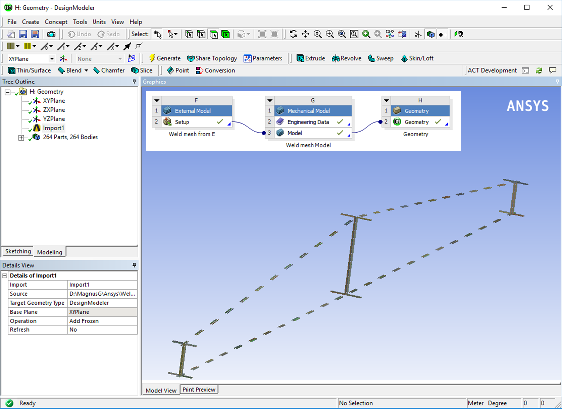
The fillet weld mesh (Solid185/Solid186) and the needed weld contacts are created during solution. Set “Export Weld Group Cdb = Yes” in the Add Weld Settings to export the weld mesh from the “Fillet Welds Group” to the Ansys cdb file “FilletWeldGroup.cdb” in the “Solver Files Directory”. Read the cdb file in an “External Model” and link the “Setup” cell to the “Model” cell of a “Mechanical Model” and finally link it to a “Geometry” system to export to a target geometry format.
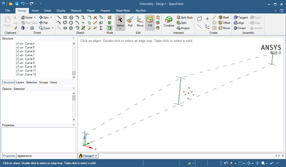
Individual weld lines can also be imported into Space Claim or Design Modeler. See the “Export Weld Line” option for the weld objects.
 App default material
Weld Toolkit contains a list of default materials for use with weld. The material properties are saved in a “dictionary” in the app installation folder in the file “Materials.json”. This file can be edited using e.g. Visual Studio Code or other text editors with plugins for “json” format.
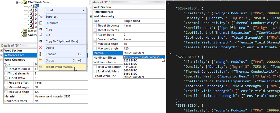
The selected weld material (from Engineering Data) can be exported and included in the app default materials.
Right-click on a weld and select “Export Weld Material” to export the selected weld material (from Engineering Data) to be included in the app default materials and be available for future analyses.
When installing a new version of Weld Toolkit you may can import your custom materials using the Import Weld Settings.
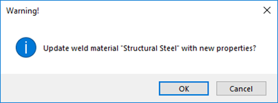
If the Engineering Data material name already exists in the weld material list you get the option to update the material with the new properties defined in Engineering Data. If exporting a default material, e.g. “S235-BISO” nothing happens.
The properties “Tensile Yield Strength” (Ry) and “Ultimate Yield Strength” (Rm) if defined are used in weld Result when post processing Eurocode 3. These properties are not to be confused with the yield limit used in isotropic and kinematic hardening plasticity material models.
The structural material properties for the default materials are listed in the following table.
All weld materials uses the same linear properties.
- Young’s modulus: 200 GPa
- Poisson’s ratio: 0.3
- Density: 7850 kg/m3
- Coefficient of Thermal Expansion: 1.2e-05 -/C
- Thermal Conductivity: 60.5 W/(m*C)
- Specific Heat: 434 J/(kg*C)
The “Bilinear Isotropic Hardening” (BISO) uses the “Tensile Yield Strength” (Ry) as the yield limit and a tangent modulus of 1000 MPa.
| Material Name | Ry [MPa] | Rm [MPa] |
|---|---|---|
| S235-BISO | 235 | 360 |
| S275-BISO | 275 | 410 |
| S355-BISO | 355 | 470 |
| S420-BISO | 420 | 520 |
| S460-BISO | 460 | 540 |
Add Butt Welds
The “Add Butt Weld” is identical to “Add Fillet Weld” in all properties except for the “Weld Geometry Type”. Two geometries are available: “V-Butt Weld” and “Bevel Butt Weld”. In both cases the base geometry is assumed to have a chamfer where the weld material is placed, and a face connected to the weld section edge that defines the weld direction. The weld geometry is identified based on the angle between these two faces. The graphics display the throat thickness from the weld root up to the surface and the weld surface outline.
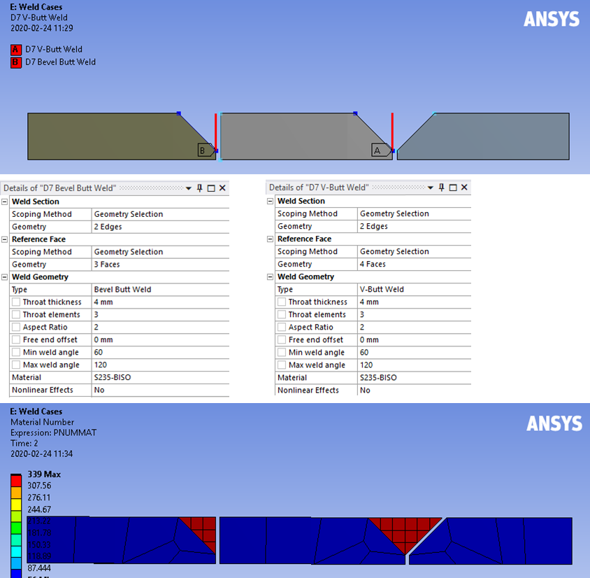
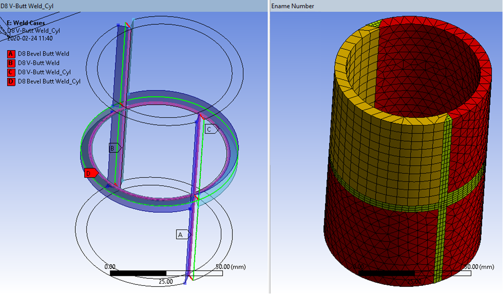
Curved and cylindrical geometry is also supported.
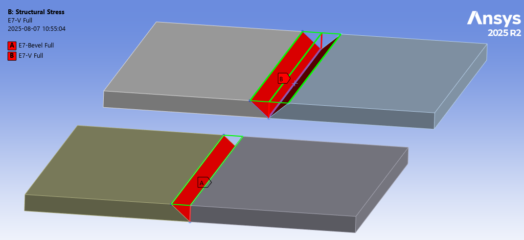
New in 2025 R2 is that the chamfer may be defined as “full penetration” over the full plate thickness.

 Virtual Fillet/Butt Welds
About
The Virtual Fillet/Butt Welds are load features similar to the Add Fillet/Butt Welds where weld seams are created and placed in a group folder in the current static or modal analysis. The weld object is used to define all weld seams to provide a visual representation of all welds as well as check that there is no double definitions of welds using section edges from an Add Weld.
The weld object also writes a details table used in the Weld Report. It also provides context actions to add Weld Section Sizing to the Mesh and Weld Strength or Weld Fatigue results to the Solution.
Usage
Right click on the Fillet Welds Group folder and select “Add Virtual Fillet Welds” . You can also use “Duplicate” on an existing Weld and modify the properties.
The Virtual Welds can be added or modified after the analysis is solved to organize the model and simplify post processing.
Inputs to define the Virtual Fillet/Butt Welds are:
| Weld Section | |
|---|---|
| Scoping Method | Geometry Selection (Default)/Named Selection (i) |
| Geometry | Weld section edges along the weld seam root. |
| Reference Face | |
| Scoping Method | Geometry Selection (Default)/Named Selection |
| Geometry | Reference Faces connected to the Weld Section edges. |
| Weld Geometry | |
| Geometry select | Manual select (no weld)/Manual select weld part (ii) |
| Type (Fillet weld) | Single sided (Default)/Double sided/Single sided intermittent/Double sided intermittent (iii) |
| Type (Butt weld) | Butt weld (Default)/Butt weld intermittent/Butt weld Double/Butt weld Double sided intermittent (iii) |
| Weld side | Top (Default)/Bottom/Reference Face (iv) |
| Throat thickness | Weld throat thickness, a < 100 mm (Default 3 mm *) |
| Free end offset | Inactive weld length on an open weld chain (Default 0 mm). Used to calculate total effective weld length. |
| Weld fraction (iii) | Ratio of Total Weld Length to Total Section Length, Lweld/Lsection. |
| Manual plate thickness | Assign a manual solid plate thickness for “Double sided” welds (Default 0 mm). |
| Material | None (Default). Select material from “Engineering Data” or app default materials (v). |
| Total Weld Length | Length of the weld seam Lweld to help estimate welding time and cost (Read only). |
(*) Default values
Default values for these properties are defined in the Weld Settings.
(i) Scoping Method
The manual “Geometry Selection” can be converted to a “Named Selection” using the context action “Promote to Named Selection”. Do not use the same Weld Section in both a Virtual Fillet Weld and a Virtual Butt Weld!
(ii) Geometry select
The option “Manual select (no weld)” is used for shell and solid models without a physical weld part. The option “Manual select weld part” must be used when selecting a fillet weld part, corresponding to the Type “Solid model (weld part)”.
The Weld side may need to be modified depending on if contact or shared topology is used.
(iii) Intermittent
Selecting Type = “… intermittent” displays these properties.
(iv) Weld side
For a Virtual Butt Weld the option “Weld side = Reference Face” is used to select the Reference Face as the location where the forces are extracted. This is useful if the section is not perpendicular to the top face or to evaluate a “laser weld” imprint connecting two planar parts via a bonded contact.
(v) Material
The Material name is only used if creating a Weld Strength or Weld Fatigue result using the corresponding context action.
 Group Features
The Group object is used to collect and organize the individual types of welds. It is possible to insert more than one Group object using the context action “Insert>Fillet/Butt Welds Group” on the selected “Analysis”.
| Definition | |
|---|---|
| Show Geometry | Yes (Default)/No. Enable Group view of all group children. (i) |
| Show Geometry on Results | Yes/No (Default). Plot weld geometry on results. |
| Show Id number | Yes/No (Default). Plot weld section Id number. |
| Show Weld Coordinate System | Yes/No (Default). Plot Weld coordinate system at weld section start vertex. |
| Weld Configuration Source | None (Default) Click to select a Weld Configuration Source file. |
(i) The graphics of all Weld geometry is cashed in memory to speed up the show/hide of objects. When hiding a weld object it will not clear graphics for other apps or Mechanical scripts. If the graphics gets “stuck” you can set the General Settings to “Show Geometry = No” to clear all graphics and then set it to “Yes” again.
Weld edge sizing, Strength or Hot-Spot fatigue result objects for all welds in the Weld Group or a selected Weld object can be added using the context actions “Add Section Edge Sizing”, “Add Fillet/Butt Weld Strength” and “Add Hot-Spot Stress Fatigue” respectively.
Weld Configuration Source
This property is hidden by default but is useful if using “Model Assembly” to combine models.
When Importing a Weld Configuration to the Analysis this property becomes visible and file name is displayed. If the source configuration file is updated the changes can be applied by the context action “Update Group from Source”.
- The group name must be unique and match one name in the source file of the same type, otherwise nothing is updated.
- An existing child in the group is updated if the child name is unique and matches one child in the source file.
- Additional children from the source file are added if they are missing in the group.
- Existing children that are not in the source file are left unchanged.
The property visibility can be toggled by the context action “Reset Configuration File”.
When hiding the property the source file name is reset to “None”.
When an analysis is solved the Save Weld Configuration is executed.
When opening a project that uses the Weld Configuration Source feature a “?” may appear on the Group and its children and the Solution.
To remove the “?” toggle e.g. the “Show Id number” to avoid invalidate the solution.