 Supported Features
Table of contents
Analysis Systems
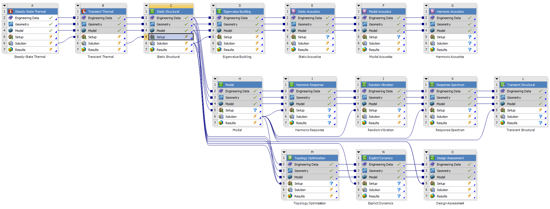
The number of supported analysis systems covers all Mechanical, Thermal and Acoustic systems and includes “Initial Conditions” and “Analysis Settings”.

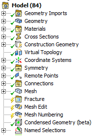
Model Objects

- Geometry Imports
- Geometry Import
- Geometry
- Body/Part
- Point Mass
- Distributed Point Mass
- Thermal Point Mass
- Surface Coating
- Thickness
- Materials
- Material Assignment
- Virtual Topology
- Construction Geometry
- Path/Surface/Solid/Line
- Coordinate Systems/Coordinate System
- (Symmetry)
- Remote Points
- Remote Point
- Connections
- Contacts/Contact
- Joints/Joint
- Body Interactions
- Body Interaction
- (Contact Tool)
- Mesh
- Weld mesh
- Fracture
- Semi-Elliptical Crack
- Arbitrary Crack
- Pre-Meshed Crack
- Interface Delamination
- SMART Crack Growth
- Mesh Edit
- Pull(Extrude)
- Mesh Numbering
- Numbering
- Condensed Geometry
- Condensed Part
- Imported Condensed Part
- Named Selections
- Named Selection
Objects put in between brackets only output the basic information, i.e. the object name as the header and comments and figures.
Analysis Objects
Basic output for an analysis object is the object name as the header and comments and figures. Objects put in between brackets only output the basic information.
- Analysis Settings
- Initial Conditions
- Pre-Stress
- Initial Temperature
- Velocity
- Angular Velocity
- Drop Height
- Inertial
- Acceleration
- Standard Earth Gravity
- Rotational Velocity
- Rotational Acceleration
- Loads
- Pressure
- Pipe Pressure
- Hydrostatic Pressure
- Force
- Remote Force
- Bearing Load
- Bolt Pretension
- Moment
- Line Pressure
- Thermal Condition
- Pipe Temperature
- Temperature
- Convection
- Radiation
- Heat Flow
- Heat Flux
- Supports
- Fixed Support
- Displacement
- Remote Displacement
- Frictionless Support
- Compression Only Support
- Cylindrical Support
- Simply Supported
- Fixed Rotation
- Elastic Support
- (Conditions)
- Direct FE
- Nodal Orientation
- Nodal Force
- Nodal Pressure
- Nodal Displacement
- Nodal Rotation
- EM Transducer
- ACT Loads
Objects put in between brackets only output the basic information, i.e. the object name as the header and comments and figures.
ACT Loads
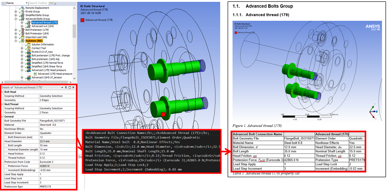
Properties from any ACT load objects can be displayed in a table if the ACT object writes a property file to the solution folder with name (using Python syntax):
loadFileName = “UserDefinedLoad_” + str(load.ObjectId) + “.prop”

Bolt Toolkit and Weld Toolkit has this feature.
Solution Objects
- Solution Information
- Modal; Frequency list & Participation factors
- Deformation
- Strain
- Stress
- (Energy)
- (Damage)
- Linearized Stress
- (Volume)
- Probe
- Frequency Response chart (Stress, Strain, Def, Velo., Acc.)
- Tools
- Stress Tool
- Fatigue Tool
- Contact Tool
- Bolt Tool
- Beam Tool
- Fracture Tool
- (Composite Failure Tool)
- Response PSD Tool
- (Expansion Settings)
- Solution Combination
- (Fatigue Combination)
- Chart of result objects
- ACT Results
Objects put in between brackets only output the basic information, i.e. the object name as the header and comments and figures.
ACT Results
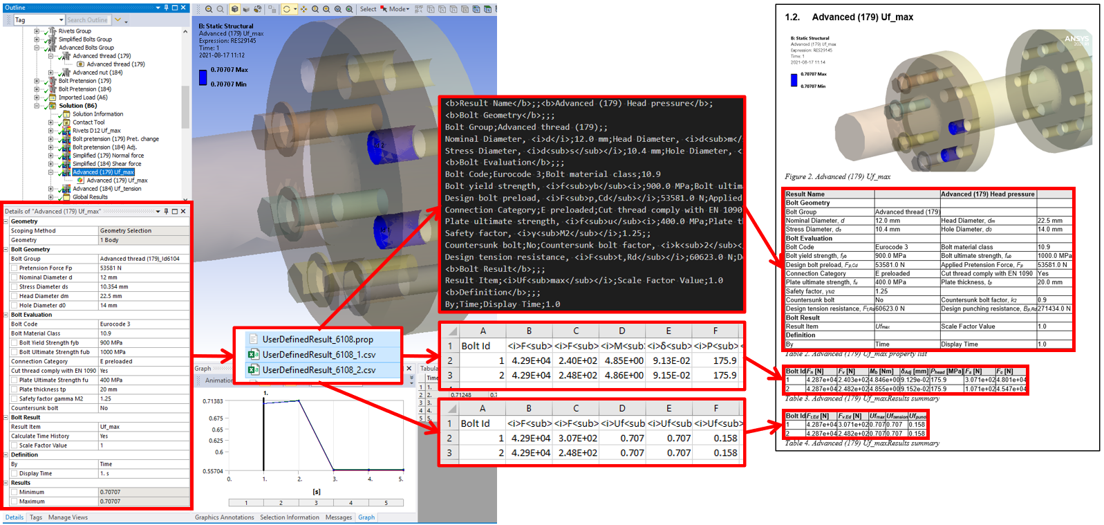
Properties and results from any ACT result objects can be displayed in table(s) if the ACT object writes a property (.prop) and optional csv files to the solution folder with name:
resultFileName = “UserDefinedResult_” + str(result.ObjectId) + “.prop”
resultFileName = “UserDefinedResult_” + str(result.ObjectId) + “.csv”
resultFileName = “UserDefinedResult_” + str(result.ObjectId) + “_1.csv”
resultFileName = “UserDefinedResult_” + str(result.ObjectId) + “_2.csv”

Bolt Toolkit and Weld Toolkit has this feature.