Material Variation Documentation
 Material Variation
About
The Material Variation object creates a linear variation of material properties over a part of a body.
Usage
-
Define the two materials used for interpolation in the Engineering Data tab on the project page.
-
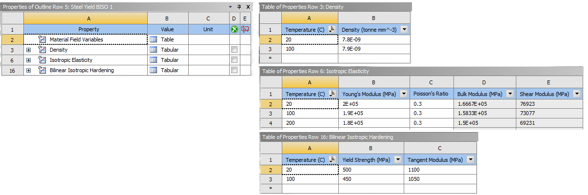
The two materials must have the same mechanical and thermal properties but may have different values.
-
If the property is a function of temperature, the table of temperature values must be the same for both materials.
Different properties (e.g. DENS, EX, NUXY, C, KXX) may have different temperature tables. -
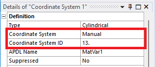
Define a Coordinate System (Cartesian or Cylindrical) where one Axis aligns with the material variation of the body.
The system must use “Manual” assigned “Coordinate System Id”.
-
Click the “Material Variation” button to add to the current selected solution (Structural or Thermal).
Inputs to define the Material Variation are:
| Geometry | |
|---|---|
| Scoping Method | Geometry Selection/Named Selection |
| Geometry | One Body |
| Variation Definition | |
| Coordinate System | Coordinate system selection |
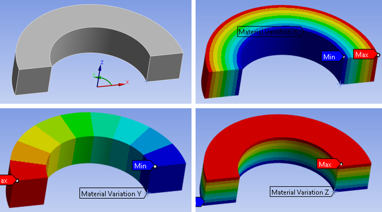
| Axis | X (Default)/Y/Z Axis to define start and end location. |
| Start location | Start coordinate in selected Axis (i) |
| End location | End coordinate in selected Axis (i) |
| Discrete Property Bands | Number of material layers (Default 10) (ii) |
| Material Properties Definition | (iii) |
| Material 1 | Material selection 1 |
| Material 2 | Material selection 2 |
(i) Start and End Location
If selecting “Axis = Y” in a cylindrical system, the “Start” and “End” value is taken as the angle in degrees in the range from -180 to 180.
(ii) Discrete Property Bands
The number of regions in the mesh where interpolated material models are placed. A higher number means more accuracy but may also require a finer mesh to accurately capture the variation. Within each region the material properties are constant.
(iii) Material Properties Definition
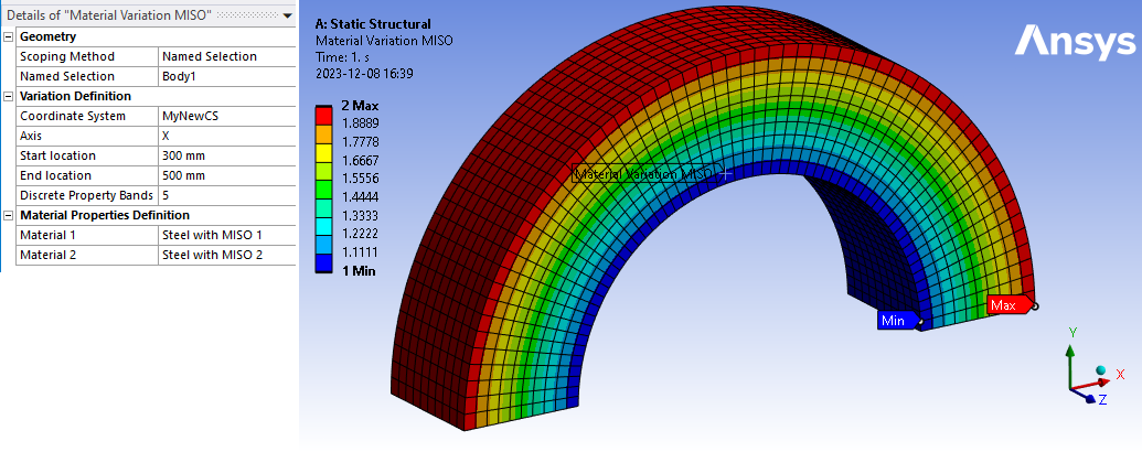
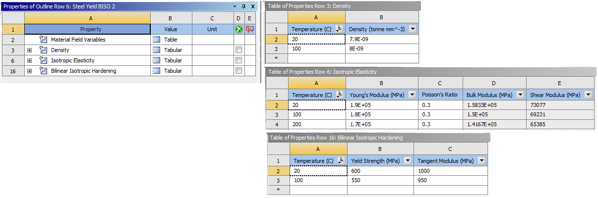
Example material 1 “Steel Yield BISO 1”
Example material 2 “Steel Yield BISO 2”
Tips
-
Several material variation objects can be used in the same analysis, but only one can be scoped to the same body.
-
The mesh should be reasonably fine in the variation region to accurately capture the change in material properties. At least one element per Discrete Property Band is recommended.
-
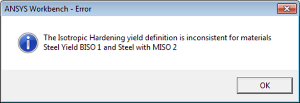
Plastic material models may also be used, but they must use the same type of yield definition.
Graphics
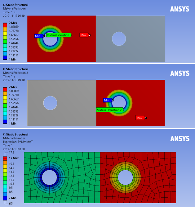
The variation will be displayed as a smooth contour in Mechanical once the mesh is available. The contour value shows the interpolation value between the two material models (1 and 2). Note that Mechanical uses a fixed number of contour bands and this does not reflect the number of Discrete Property Bands.
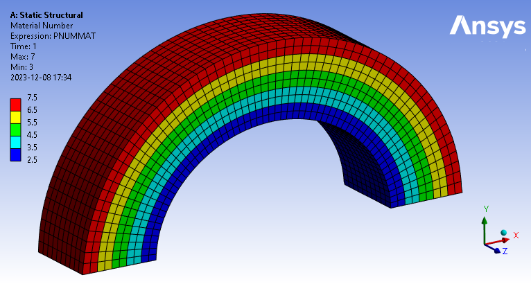
 Rst Material Number
The actual material assignment numbers can be plotted using “Rst Material Number” once the model is solved. Properties are constant within each of these bands (5 discrete property bands used on the model shown). Note that the contour is set from 2.5 to 7.5 in the figure below so each material gets a unique colour.