Initial Deformation Documentation
 Initial Deformation
About
The Initial Deformation object defines the result steps and weight factors from linked analyses to calculate an initial deformation of the structure without breaking the link to Geometry and Model.
Usage
-
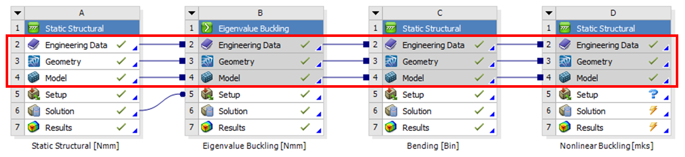
Create an analysis system with shared Engineering Data, Geometry and Model.
-
The source systems may be solved in different solver units and will be converted to the current solution unit. Source systems may be Static, Transient, Modal and Buckling.
-
Click the “Initial Deformation” button to add to the current selected solution (Static Structural or Thermal).
If the linked source systems are updated with new loads etc. you must manually clear the Initial Deformation system and re-solve. The system does not detect if a source system is modified.
Inputs to define the Initial Deformation are:
| Definition | |
|---|---|
| Max Initial Deformation | Magnitude of the initial deformation. |
| Result Set Table | Tabular Data editor to define Analysis, Time and Weight |
| Advanced | |
| Use UPGEOM Command | Yes/No (Default) Read deformations during solution or write them to the input file. |
| Copy RST file(s) to workdir | Yes/No (Default) Visible if “Use UPGEOM Command = Yes” |
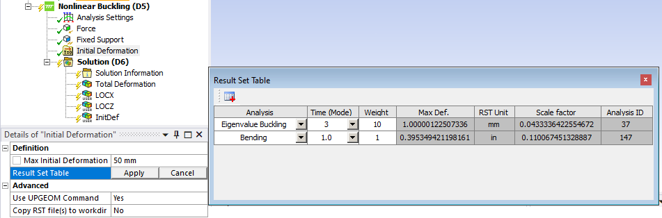
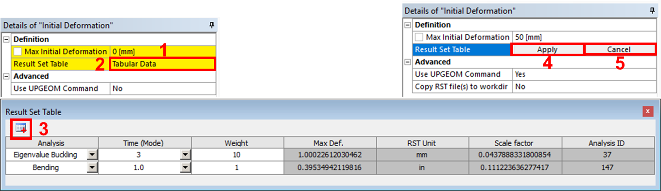
- Enter desired magnitude of the initial deformation, “Max Initial Deformation”.
- Click on “Tabular Data” to edit the load case combination.
- Click on “Add Row” to select Analysis, Time (Mode) and Weight.
Note: Weight may be both positive or negative to set the direction of the deformation. - Click “Apply” to read in the results and calculate the “Scale Factor”.
To see the “Max Def.” and “Scale factor” click on “Tabular Data” again. - Click “Cancel” to close the tabular editor without saving the data.
Do not click the red “Close window” button!
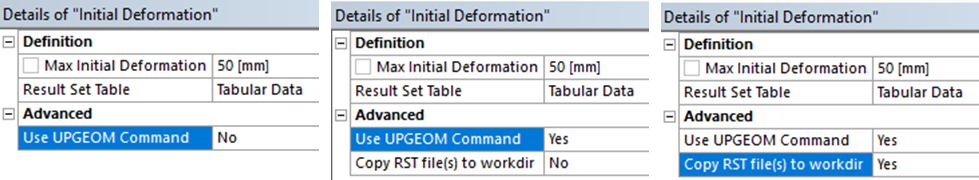
Advanced
The Initial Deformation can be applied in two different ways using “Use UPGEOM Command”.
-
No: Modify the nodal coordinates using the “NMODIF” command (default).
This option will write the new node coordinates in the solver input file (ds.dat), hence copy information from the result files to the input file before sending the file to the solver on either local PC or remote using RSM. -
Yes: Update the nodal coordinates using the “UPGEOM” command to read the deformations directly from the source result files (file.rst) during solution.
This option needs direct access to the source results files as only a file reference command is written in the input file.
“Copy RST file(s) to workdir = No”: When solving on local PC.
“Copy RST file(s) to workdir = Yes”: When solving remote using RSM.
If the Initial Deformation analysis contains user defined nodes from Commands or ACT objects you must set “Use UPGEOM Command = Yes” otherwise only the Mesh and Remote Point nodes are updated.
When using “Use UPGEOM Command = Yes” make sure to use predefined Remote Points for all remote forces/displacements and also to use the same unit system in all analyses!
The app now checks if the remote points are suppressed or un-used to prevent errors when updating the mesh during solution.
Verification
In the Downloads section there is a demo model used in the this verification analysis.
The image below shows the two deformation shapes (1, 2) and the defined Initial Deformation (3) and the resulting total deformation (4).
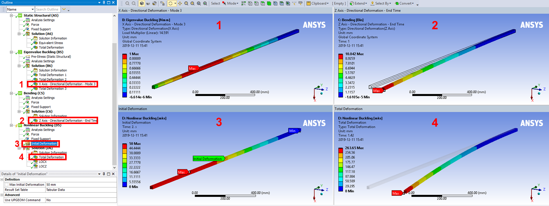
A comparison between hand calculation and the app is done in the following steps.
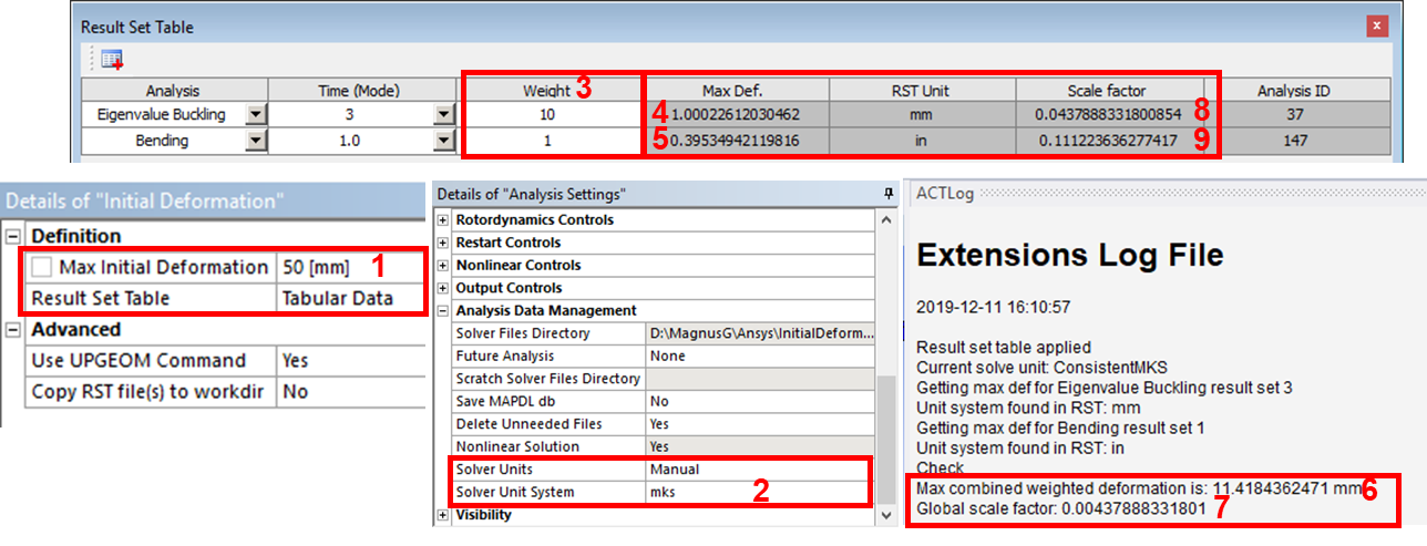
- In this example a total magnitude of 50 mm is defined as Max Initial Deformation.
- Solver Units is set to “mks”.
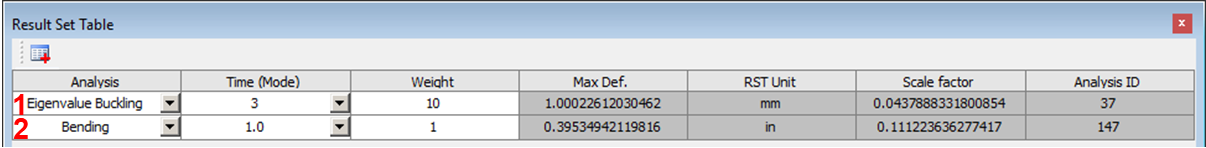
- The Weight factor is used to mix multiple load cases together. (For single load case Weight = 1)
- Eigenvalue Buckling Mode 3 has Max Def. = 1.00 mm (in X direction) & Weight factor = 10 => Row max def.: 10 mm.
- Bending Time 1.0 has Max Def. = 0.395” (in Z direction) & Weight factor 1 => Row max def.: 10 mm.
- Max combined deformation ~ sqrt(10^2 + 10^2) = 14.1 mm. Actual Max combined weighted deformation: 11.4 mm.
(If row 2 has different unit the deformation is converted when combining the results. - Global Scale factor: 0.050[m]/11.4 = 0.00438 (Factor to multiply the combined deformation to get correct magnitude).
- Eigenvalue Buckling Scale factor: 10*0.00438 = 0.0438 (Factor used to multiply individual result set if using UPGEOM).
- Bending Scale factor: 25.4[mm/in]*0.00438 = 0.111 (Convert inch to mm so weight is correct).